Toyota CH-R Service Manual: Seat Heater for Front Right Seat does not Operate
DESCRIPTION
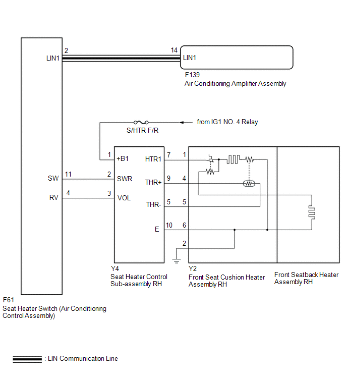
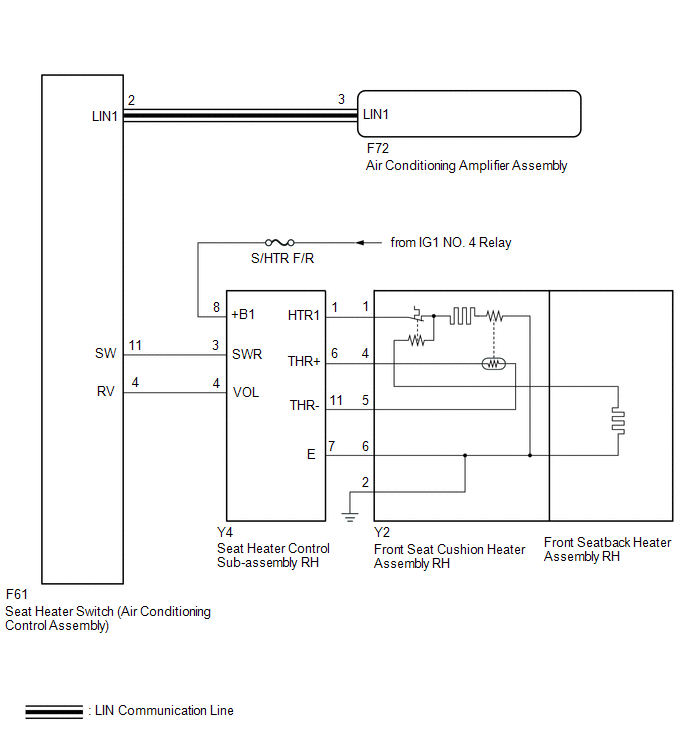
When the seat heater switch on air conditioning control assembly is operated, the seat heater control sub-assembly RH receives the signal. The seat heater control sub-assembly RH receives the signal and operates the front seat heater.
WIRING DIAGRAM
for TMC Made
for TMMT Made
CAUTION / NOTICE / HINT
NOTICE:
- If the battery voltage is low, the seat heater system may not operate.
Refer to Data List for the power steering system.
Click here
.gif)
- Inspect the fuses for circuits related to this system before performing the following procedure.
PROCEDURE
|
1. |
CLEAR DTC |
(a) Clear the DTCs.
Click here
|
.gif)
|
2. |
CHECK FOR DTC |
(a) Check for DTCs.
Click here
OK:
DTC B14B5 is not output.
|
Result |
Proceed to |
|---|---|
|
OK (for TMC Made) |
A |
|
OK (for TMMT Made) |
B |
|
NG |
C |
| B | .gif) |
GO TO STEP 12 |
| C | |
GO TO DIAGNOSTIC TROUBLE CODE CHART |
|
|
3. |
CHECK HARNESS AND CONNECTOR (IG POWER SUPPLY - SEAT HEATER CONTROL SUB-ASSEMBLY RH) |
|
(a) Disconnect the seat heater control sub-assembly RH connector. |
|
(b) Measure the voltage according to the value(s) in the table below.
Standard Voltage:
|
Tester Connection |
Switch Condition |
Specified Condition |
|---|---|---|
|
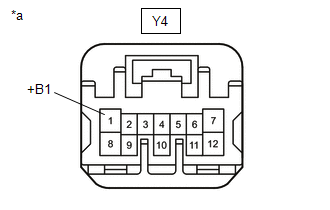
Y4-1 (+B1) - Body ground |
Ignition switch ON |
11 to 14 V |
|
Ignition switch off |
Below 1 V |
| NG | |
REPAIR OR REPLACE HARNESS OR CONNECTOR |
|
|
4. |
CHECK HARNESS AND CONNECTOR (SEAT HEATER CONTROL SUB-ASSEMBLY RH - FRONT SEAT CUSHION HEATER ASSEMBLY RH - BODY GROUND) |
(a) Disconnect the Y4 seat heater control sub-assembly RH connector.
(b) Disconnect the Y2 front seat cushion heater assembly RH connector.
(c) Measure the resistance according to the value(s) in the table below.
Standard Resistance:
|
Tester Connection |
Condition |
Specified Condition |
|---|---|---|
|
Y4-7 (HTR1) - Y2-1 |
Always |
Below 1 Ω |
|
Y4-9 (THR+) - Y2-4 |
Always |
Below 1 Ω |
|
Y4-5 (THR-) - Y2-5 |
Always |
Below 1 Ω |
|
Y4-10 (E) - Y2-6 |
Always |
Below 1 Ω |
|
Y2-2 - Body ground |
Always |
Below 1 Ω |
|
Y4-7 (HTR1) or Y2-1 - Body ground |
Always |
10 kΩ or higher |
|
Y4-9 (THR+) or Y2-4 - Body ground |
Always |
10 kΩ or higher |
|
Y4-5 (THR-) or Y2-5 - Body ground |
Always |
10 kΩ or higher |
|
Y4-10 (E) or Y2-6 - Body ground |
Always |
10 kΩ or higher |
| NG | |
REPAIR OR REPLACE HARNESS OR CONNECTOR |
|
|
5. |
INSPECT FRONT SEAT CUSHION HEATER ASSEMBLY RH |
(a) Remove the front seat cushion heater assembly RH.
Click here
(b) Inspect the front seat cushion heater assembly RH.
Click here
| NG | |
REPLACE FRONT SEAT CUSHION HEATER ASSEMBLY RH |
|
|
6. |
INSPECT FRONT SEATBACK HEATER ASSEMBLY RH |
(a) Remove the front seatback heater assembly RH.
Click here
(b) Inspect the front seatback heater assembly RH.
Click here
| NG | |
REPLACE FRONT SEATBACK HEATER ASSEMBLY RH |
|
|
7. |
CHECK HARNESS AND CONNECTOR (SEAT HEATER SWITCH (AIR CONDITIONING CONTROL ASSEMBLY) - SEAT HEATER CONTROL SUB-ASSEMBLY RH) |
(a) Disconnect the F61 seat heater switch (air conditioning control assembly) connector.
(b) Disconnect the Y4 seat heater control sub-assembly RH connector.
(c) Measure the resistance according to the value(s) in the table below.
Standard Resistance:
|
Tester Connection |
Condition |
Specified Condition |
|---|---|---|
|
F61-11 (SW) - Y4-2 (SWR) |
Always |
Below 1 Ω |
|
F61-4 (RV) - Y4-3 (VOL) |
Always |
Below 1 Ω |
|
F61-11 (SW) or Y4-2 (SWR) - Body ground |
Always |
10 kΩ or higher |
|
F61-4 (RV) or Y4-3 (VOL) - Body ground |
Always |
10 kΩ or higher |
| NG | |
REPAIR OR REPLACE HARNESS OR CONNECTOR |
|
|
8. |
REPLACE SEAT HEATER CONTROL SUB-ASSEMBLY RH |
(a) Temporarily replace the heater control sub-assembly RH with a new or known good one.
Click here
|
|
9. |
CHECK SEAT HEATER SYSTEM OPERATION |
(a) Check that the seat heater system is operated normally.
OK:
The seat heater system is operated normally.
| OK | |
END (SEAT HEATER CONTROL SUB-ASSEMBLY WAS DEFECTIVE) |
|
|
10. |
REPLACE SEAT HEATER SWITCH (AIR CONDITIONING CONTROL ASSEMBLY) |
(a) Temporarily replace the seat heater switch (air conditioning control assembly) with a new or known good one.
Click here
|
|
11. |
CHECK SEAT HEATER SYSTEM OPERATION |
(a) Check that the seat heater system is operated normally.
OK:
The seat heater system is operated normally.
| OK | |
END (SEAT HEATER SWITCH (AIR CONDITIONING CONTROL ASSEMBLY) WAS DEFECTIVE) |
| NG | |
REPLACE AIR CONDITIONING AMPLIFIER ASSEMBLY |
|
12. |
CHECK HARNESS AND CONNECTOR (IG POWER SUPPLY - SEAT HEATER CONTROL SUB-ASSEMBLY RH) |
|
(a) Disconnect the seat heater control sub-assembly RH connector. |
|
(b) Measure the voltage according to the value(s) in the table below.
Standard Voltage:
|
Tester Connection |
Switch Condition |
Specified Condition |
|---|---|---|
|
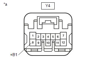
Y4-8 (+B1) - Body ground |
Ignition switch ON |
11 to 14 V |
|
Ignition switch off |
Below 1 V |
| NG | |
REPAIR OR REPLACE HARNESS OR CONNECTOR |
|
|
13. |
CHECK HARNESS AND CONNECTOR (SEAT HEATER CONTROL SUB-ASSEMBLY RH - FRONT SEAT CUSHION HEATER ASSEMBLY RH - BODY GROUND) |
(a) Disconnect the Y4 seat heater control sub-assembly RH connector.
(b) Disconnect the Y2 front seat cushion heater assembly RH connector.
(c) Measure the resistance according to the value(s) in the table below.
Standard Resistance:
|
Tester Connection |
Condition |
Specified Condition |
|---|---|---|
|
Y4-1 (HTR1) - Y2-1 |
Always |
Below 1 Ω |
|
Y4-6 (THR+) - Y2-4 |
Always |
Below 1 Ω |
|
Y4-11 (THR-) - Y2-5 |
Always |
Below 1 Ω |
|
Y4-7 (E) - Y2-6 |
Always |
Below 1 Ω |
|
Y2-2 - Body ground |
Always |
Below 1 Ω |
|
Y4-1 (HTR1) or Y2-1 - Body ground |
Always |
10 kΩ or higher |
|
Y4-6 (THR+) or Y2-4 - Body ground |
Always |
10 kΩ or higher |
|
Y4-11 (THR-) or Y2-5 - Body ground |
Always |
10 kΩ or higher |
|
Y4-7 (E) or Y2-6 - Body ground |
Always |
10 kΩ or higher |
| NG | |
REPAIR OR REPLACE HARNESS OR CONNECTOR |
|
|
14. |
INSPECT FRONT SEAT CUSHION HEATER ASSEMBLY RH |
(a) Remove the front seat cushion heater assembly RH.
Click here
(b) Inspect the front seat cushion heater assembly RH.
Click here
| NG | |
REPLACE FRONT SEAT CUSHION HEATER ASSEMBLY RH |
|
|
15. |
INSPECT FRONT SEATBACK HEATER ASSEMBLY RH |
(a) Remove the front seatback heater assembly RH.
Click here
(b) Inspect the front seatback heater assembly RH.
Click here
| NG | |
REPLACE FRONT SEATBACK HEATER ASSEMBLY RH |
|
|
16. |
CHECK HARNESS AND CONNECTOR (SEAT HEATER SWITCH (AIR CONDITIONING CONTROL ASSEMBLY) - SEAT HEATER CONTROL SUB-ASSEMBLY RH) |
(a) Disconnect the F61 seat heater switch (air conditioning control assembly) connector.
(b) Disconnect the Y4 seat heater control sub-assembly RH connector.
(c) Measure the resistance according to the value(s) in the table below.
Standard Resistance:
|
Tester Connection |
Condition |
Specified Condition |
|---|---|---|
|
F61-11 (SW) - Y4-3 (SWR) |
Always |
Below 1 Ω |
|
F61-4 (RV) - Y4-4 (VOL) |
Always |
Below 1 Ω |
|
F61-11 (SW) or Y4-3 (SWR) - Body ground |
Always |
10 kΩ or higher |
|
F61-4 (RV) or Y4-4 (VOL) - Body ground |
Always |
10 kΩ or higher |
| NG | |
REPAIR OR REPLACE HARNESS OR CONNECTOR |
|
|
17. |
REPLACE SEAT HEATER CONTROL SUB-ASSEMBLY RH |
(a) Temporarily replace the heater control sub-assembly RH with a new or known good one.
Click here
|
|
18. |
CHECK SEAT HEATER SYSTEM OPERATION |
(a) Check that the seat heater system is operated normally.
OK:
The seat heater system is operated normally.
| OK | |
END (SEAT HEATER CONTROL SUB-ASSEMBLY WAS DEFECTIVE) |
|
|
19. |
REPLACE SEAT HEATER SWITCH (AIR CONDITIONING CONTROL ASSEMBLY) |
(a) Temporarily replace the seat heater switch (air conditioning control assembly) with a new or known good one.
Click here
|
|
20. |
CHECK SEAT HEATER SYSTEM OPERATION |
(a) Check that the seat heater system is operated normally.
OK:
The seat heater system is operated normally.
| OK | |
END (SEAT HEATER SWITCH (AIR CONDITIONING CONTROL ASSEMBLY) WAS DEFECTIVE) |
| NG | |
REPLACE AIR CONDITIONING AMPLIFIER ASSEMBLY |
 Lost Communication with Front Seat Temperature Adjustment Switch LIN (B14B5)
DESCRIPTION
The seat heater switch (air conditioning control assembly) communicates with
the air conditioning amplifier assembly via LIN communication.
If the LIN communication system is malfuncti ...
 Seat Heater for Front Left Seat does not Operate
DESCRIPTION
When the seat heater switch on air conditioning control assembly is operated,
the seat heater control sub-assembly LH receives the signal. The seat heater control
sub-assembly LH rece ...
Other materials:
Toyota CH-R Service Manual > Brake Fluid: Bleeding
BLEEDING
CAUTION / NOTICE / HINT
NOTICE:
Move the shift lever to P and apply the parking brake before bleeding
the brakes.
Add brake fluid to keep the level between the MIN and MAX lines of the
reservoir while bleeding the brakes.
If brake fluid leaks onto any painted surf ...
Toyota CH-R Service Manual > Front Evaporator Temperature Sensor(for Denso Made): Inspection
INSPECTION
PROCEDURE
1. INSPECT NO. 1 COOLER THERMISTOR
(a) Check the resistance.
(1) Measure the resistance according to the value(s) in the table below.
*a
Component without harness connected
(No. 1 Cooler Thermistor)
*b
Sensing Portion
...
Toyota C-HR (AX20) 2023-2026 Owner's Manual
Toyota CH-R Owners Manual
- For safety and security
- Instrument cluster
- Operation of each component
- Driving
- Interior features
- Maintenance and care
- When trouble arises
- Vehicle specifications
- For owners
Toyota CH-R Service Manual
- Introduction
- Maintenance
- Audio / Video
- Cellular Communication
- Navigation / Multi Info Display
- Park Assist / Monitoring
- Brake (front)
- Brake (rear)
- Brake Control / Dynamic Control Systems
- Brake System (other)
- Parking Brake
- Axle And Differential
- Drive Shaft / Propeller Shaft
- K114 Cvt
- 3zr-fae Battery / Charging
- Networking
- Power Distribution
- Power Assist Systems
- Steering Column
- Steering Gear / Linkage
- Alignment / Handling Diagnosis
- Front Suspension
- Rear Suspension
- Tire / Wheel
- Tire Pressure Monitoring
- Door / Hatch
- Exterior Panels / Trim
- Horn
- Lighting (ext)
- Mirror (ext)
- Window / Glass
- Wiper / Washer
- Door Lock
- Heating / Air Conditioning
- Interior Panels / Trim
- Lighting (int)
- Meter / Gauge / Display
- Mirror (int)
- Power Outlets (int)
- Pre-collision
- Seat
- Seat Belt
- Supplemental Restraint Systems
- Theft Deterrent / Keyless Entry

0.0089