Toyota CH-R Service Manual: Lost Communication with Front Seat Temperature Adjustment Switch LIN (B14B5)
DESCRIPTION
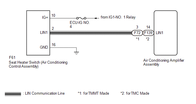
The seat heater switch (air conditioning control assembly) communicates with the air conditioning amplifier assembly via LIN communication.
If the LIN communication system is malfunctioning, the air conditioning amplifier assembly will not operate even if the seat heater switch (air conditioning control assembly) is operated.
|
DTC No. |
Detection Item |
DTC Detection Condition |
Trouble Area |
|---|---|---|---|
|
B14B5 |
Lost Communication with Front Seat Temperature Adjustment Switch LIN |
Lost communication with the seat heater switch (air conditioning control assembly) |
|
WIRING DIAGRAM
CAUTION / NOTICE / HINT
NOTICE:
- Inspect the fuses for circuits related to this system before performing the following procedure.
- When DTC B14B2 and B14B5 are output simultaneously, first perform troubleshooting
for the air conditioning system.
- for TMMT Made:
Click here
.gif)
- for TMC Made:
Click here
- for TMMT Made:
PROCEDURE
|
1. |
CLEAR DTC |
(a) Clear the DTCs.
Click here
|
.gif)
|
2. |
CHECK FOR DTC |
(a) Check for DTCs.
Click here
OK:
DTC B14B5 is not output.
| OK | .gif) |
USE SIMULATION METHOD TO CHECK |
|
|
3. |
CHECK HARNESS AND CONNECTOR (IG POWER SUPPLY - SEAT HEATER SWITCH (AIR CONDITIONING CONTROL ASSEMBLY) - BODY GROUND) |
|
(a) Disconnect the seat heater switch (air conditioning control assembly) connector. |
|
(b) Measure the voltage and resistance according to the value(s) in the table below.
Standard Voltage:
|
Tester Connection |
Switch Condition |
Specified Condition |
|---|---|---|
|
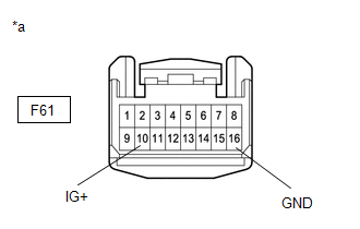
F61-10 (IG+) - Body ground |
Ignition switch ON |
11 to 14 V |
|
Ignition switch off |
Below 1 V |
(c) Measure the resistance according to the value(s) in the table below.
Standard Resistance:
|
Tester Connection |
Condition |
Specified Condition |
|---|---|---|
|
F61-16 (GND) - Body ground |
Always |
Below 1 Ω |
| NG | |
REPAIR OR REPLACE HARNESS OR CONNECTOR |
|
|
4. |
CHECK HARNESS AND CONNECTOR (AIR CONDITIONING AMPLIFIER ASSEMBLY - SEAT HEATER SWITCH (AIR CONDITIONING CONTROL ASSEMBLY)) |
(a) Disconnect the F61 seat heater switch (air conditioning control assembly) connector.
(b) Disconnect the F72*1 or F139*2 air conditioning amplifier assembly connector.
- *1: for TMMT Made
- *2: for TMC Made
(c) Measure the resistance according to the value(s) in the table below.
Standard Resistance:
for TMMT Made|
Tester Connection |
Condition |
Specified Condition |
|---|---|---|
|
F61-2 (LIN1) - F72-3 (LIN1) |
Always |
Below 1 Ω |
|
F61-2 (LIN1) or F72-3 (LIN1) - Body ground |
Always |
10 kΩ or higher |
|
Tester Connection |
Condition |
Specified Condition |
|---|---|---|
|
F61-2 (LIN1) - F139-14 (LIN1) |
Always |
Below 1 Ω |
|
F61-2 (LIN1) or F139-14 (LIN1) - Body ground |
Always |
10 kΩ or higher |
| NG | |
REPAIR OR REPLACE HARNESS OR CONNECTOR |
|
|
5. |
REPLACE SEAT HEATER SWITCH (AIR CONDITIONING CONTROL ASSEMBLY) |
(a) Temporarily replace the seat heater switch (air conditioning control assembly) with a new or known good one.
Click here
|
|
6. |
CLEAR DTC |
(a) Clear the DTCs.
Click here
OK:
DTC B14B5 is not output.
|
|
7. |
CHECK FOR DTC |
(a) Check for DTCs.
Click here
OK:
DTC B14B5 is not output.
| OK | |
END (SEAT HEATER SWITCH (AIR CONDITIONING CONTROL ASSEMBLY) WAS DEFECTIVE) |
| NG | |
REPLACE AIR CONDITIONING AMPLIFIER ASSEMBLY |
 Dtc Check / Clear
DTC CHECK / CLEAR
CHECK DTC
(a) Connect the Techstream to the DLC3.
(b) Turn the ignition switch to ON.
(c) Turn the Techstream on.
(d) Enter the following menus: Body Electrical / Air Conditione ...
 Seat Heater for Front Right Seat does not Operate
DESCRIPTION
When the seat heater switch on air conditioning control assembly is operated,
the seat heater control sub-assembly RH receives the signal. The seat heater control
sub-assembly RH rece ...
Other materials:
Toyota CH-R Service Manual > Vehicle Stability Control System: Control Module Communication Bus OFF (U0073,U0100,U0123,U0126,U0142)
DESCRIPTION
The skid control ECU (brake actuator assembly) receives signals from the ECM,
steering angle sensor, yaw rate and acceleration sensor (airbag sensor assembly)
and main body ECU (multiplex network body ECU) via CAN communication.
DTC No.
Detection Item
...
Toyota CH-R Service Manual > Steering Heater Switch: Removal
REMOVAL
PROCEDURE
1. REMOVE FRONT DOOR SCUFF PLATE LH
Click here
2. REMOVE COWL SIDE TRIM BOARD LH
Click here
3. REMOVE NO. 1 INSTRUMENT PANEL UNDER COVER SUB-ASSEMBLY
Click here
4. REMOVE INSTRUMENT CLUSTER FINISH PANEL SUB-ASSEMBLY
Click here
5. DISCONNECT HOOD LOCK CON ...
Toyota C-HR (AX20) 2023-2026 Owner's Manual
Toyota CH-R Owners Manual
- For safety and security
- Instrument cluster
- Operation of each component
- Driving
- Interior features
- Maintenance and care
- When trouble arises
- Vehicle specifications
- For owners
Toyota CH-R Service Manual
- Introduction
- Maintenance
- Audio / Video
- Cellular Communication
- Navigation / Multi Info Display
- Park Assist / Monitoring
- Brake (front)
- Brake (rear)
- Brake Control / Dynamic Control Systems
- Brake System (other)
- Parking Brake
- Axle And Differential
- Drive Shaft / Propeller Shaft
- K114 Cvt
- 3zr-fae Battery / Charging
- Networking
- Power Distribution
- Power Assist Systems
- Steering Column
- Steering Gear / Linkage
- Alignment / Handling Diagnosis
- Front Suspension
- Rear Suspension
- Tire / Wheel
- Tire Pressure Monitoring
- Door / Hatch
- Exterior Panels / Trim
- Horn
- Lighting (ext)
- Mirror (ext)
- Window / Glass
- Wiper / Washer
- Door Lock
- Heating / Air Conditioning
- Interior Panels / Trim
- Lighting (int)
- Meter / Gauge / Display
- Mirror (int)
- Power Outlets (int)
- Pre-collision
- Seat
- Seat Belt
- Supplemental Restraint Systems
- Theft Deterrent / Keyless Entry

0.0085