Toyota CH-R Service Manual: Parts Location
PARTS LOCATION
ILLUSTRATION
|
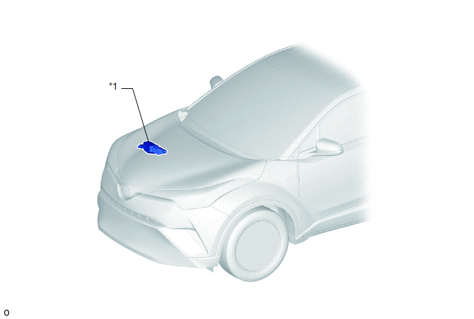
*1 |
NO. 2 ENGINE ROOM RELAY BLOCK - S/HTR F/R FUSE - S/HTR F/L FUSE |
- |
- |
ILLUSTRATION
|
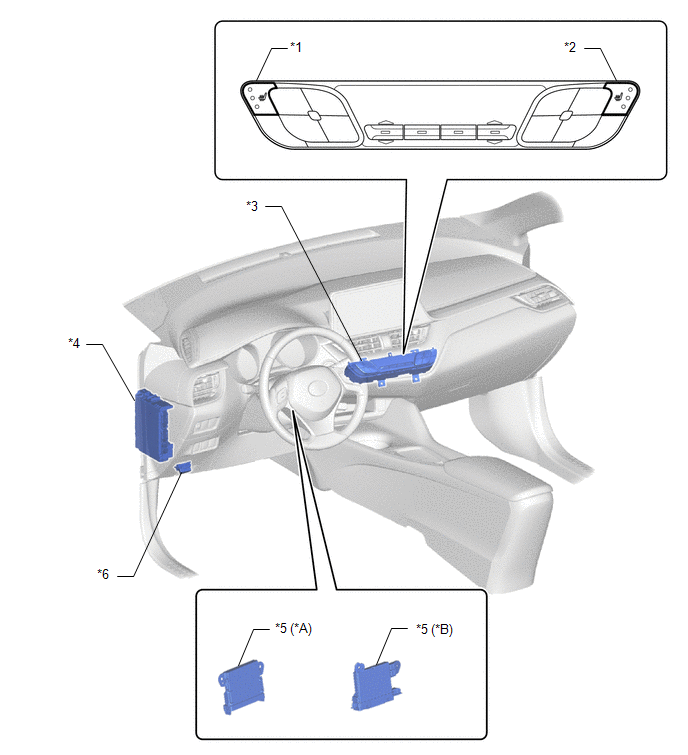
*A |
for TMMT Made |
*B |
for TMC Made |
|
*1 |
SEAT HEATER SWITCH (LH SIDE) |
*2 |
SEAT HEATER SWITCH (RH SIDE) |
|
*3 |
AIR CONDITIONING CONTROL ASSEMBLY |
*4 |
INSTRUMENT PANEL JUNCTION BLOCK ASSEMBLY - ECU-IG1 NO. 4 FUSE |
|
*5 |
AIR CONDITIONING AMPLIFIER ASSEMBLY |
*6 |
DLC3 |
ILLUSTRATION
|
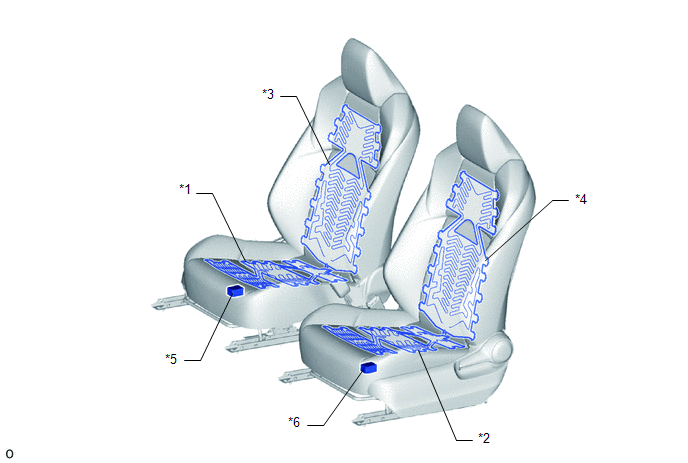
*1 |
FRONT SEAT CUSHION HEATER ASSEMBLY RH |
*2 |
FRONT SEAT CUSHION HEATER ASSEMBLY LH |
|
*3 |
FRONT SEATBACK HEATER ASSEMBLY RH |
*4 |
FRONT SEATBACK HEATER ASSEMBLY LH |
|
*5 |
SEAT HEATER CONTROL SUB-ASSEMBLY RH |
*6 |
SEAT HEATER CONTROL SUB-ASSEMBLY LH |

 System Diagram
SYSTEM DIAGRAM
...
Other materials:
Toyota CH-R Service Manual > Power Window Control System: Precaution
PRECAUTION
IGNITION SWITCH EXPRESSION
HINT:
The type of ignition switch used on this model differs according to the specifications
of the vehicle. The expressions listed in the table below are used in this section.
Expression
Ignition Switch (Position)
Engine S ...
Toyota CH-R Owners Manual > Steps to take in an emergency: If the engine will not start
If the engine will not start even though correct starting procedures
are being followed, consider each of the following points:
The engine will not start even though the starter motor operates normally.
One of the following may be the cause of the problem:
There may not be sufficient fuel in ...
Toyota C-HR (AX20) 2023-2026 Owner's Manual
Toyota CH-R Owners Manual
- For safety and security
- Instrument cluster
- Operation of each component
- Driving
- Interior features
- Maintenance and care
- When trouble arises
- Vehicle specifications
- For owners
Toyota CH-R Service Manual
- Introduction
- Maintenance
- Audio / Video
- Cellular Communication
- Navigation / Multi Info Display
- Park Assist / Monitoring
- Brake (front)
- Brake (rear)
- Brake Control / Dynamic Control Systems
- Brake System (other)
- Parking Brake
- Axle And Differential
- Drive Shaft / Propeller Shaft
- K114 Cvt
- 3zr-fae Battery / Charging
- Networking
- Power Distribution
- Power Assist Systems
- Steering Column
- Steering Gear / Linkage
- Alignment / Handling Diagnosis
- Front Suspension
- Rear Suspension
- Tire / Wheel
- Tire Pressure Monitoring
- Door / Hatch
- Exterior Panels / Trim
- Horn
- Lighting (ext)
- Mirror (ext)
- Window / Glass
- Wiper / Washer
- Door Lock
- Heating / Air Conditioning
- Interior Panels / Trim
- Lighting (int)
- Meter / Gauge / Display
- Mirror (int)
- Power Outlets (int)
- Pre-collision
- Seat
- Seat Belt
- Supplemental Restraint Systems
- Theft Deterrent / Keyless Entry

0.0081