Toyota CH-R Service Manual: Front Turn Signal Light Bulb
Components
COMPONENTS
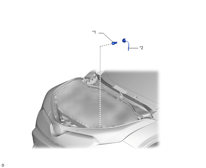
ILLUSTRATION
|
*1 |
FRONT TURN SIGNAL LIGHT BULB |
*2 |
FRONT TURN SIGNAL LIGHT SOCKET AND WIRE SUB-ASSEMBLY |
Removal
REMOVAL
CAUTION / NOTICE / HINT
HINT:
- Use the same procedure for the RH and LH sides.
- The procedure listed below is for the LH side.
PROCEDURE
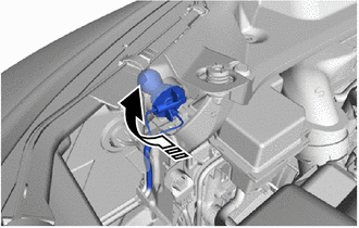
1. REMOVE FRONT TURN SIGNAL LIGHT BULB
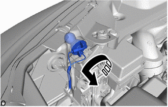
(a) Turn the front turn signal light socket and wire sub-assembly with the front turn signal light bulb as shown in the illustration to disconnect them as a unit.
.png) |
Remove in this Direction |
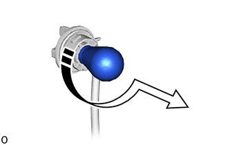
(b) Remove the front turn signal light bulb from the front turn signal light socket and wire sub-assembly as shown in the illustration.
|
|
Remove in this Direction |
Installation
INSTALLATION
CAUTION / NOTICE / HINT
HINT:
- Use the same procedure for the RH and LH sides.
- The procedure listed below is for the LH side.
PROCEDURE
1. INSTALL FRONT TURN SIGNAL LIGHT BULB
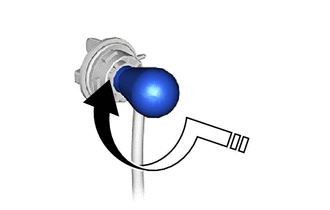
(a) Install the front turn signal light bulb to the front turn signal light socket and wire sub-assembly as shown in the illustration.
.png) |
Install in this Direction |
(b) Turn the front turn signal light socket and wire sub-assembly with the front turn signal light bulb as shown in the illustration to connect them as a unit.
|
|
Install in this Direction |
 Front Side Marker Light Bulb
Components
COMPONENTS
ILLUSTRATION
*1
FRONT SIDE MARKER LIGHT BULB
*2
FRONT SIDE MARKER LIGHT SOCKET
Removal
REMOVAL
PROCEDURE
1. REMO ...
 Front Wiper Rubber
Components
COMPONENTS
ILLUSTRATION
*1
FRONT WIPER BLADE
*2
FRONT WIPER RUBBER
Removal
REMOVAL
CAUTION / NOTICE / HINT
NOTICE:
Make su ...
Other materials:
Toyota CH-R Service Manual > Window Defogger System: How To Proceed With Troubleshooting
CAUTION / NOTICE / HINT
HINT:
Use the following procedure to troubleshoot the window defogger system.
*: Use the Techstream.
PROCEDURE
1.
VEHICLE BROUGHT TO WORKSHOP
NEXT
...
Toyota CH-R Service Manual > Pre-collision System: Stop Light Relay Circuit (C1A4B)
DESCRIPTION
The skid control ECU (brake actuator assembly) sends a stop light operation request
signal to the stop light switch assembly. If the skid control ECU (brake actuator
assembly) detects a malfunction in the stop light switch assembly circuit, the millimeter
wave radar sensor assembl ...
Toyota C-HR (AX20) 2023-2026 Owner's Manual
Toyota CH-R Owners Manual
- For safety and security
- Instrument cluster
- Operation of each component
- Driving
- Interior features
- Maintenance and care
- When trouble arises
- Vehicle specifications
- For owners
Toyota CH-R Service Manual
- Introduction
- Maintenance
- Audio / Video
- Cellular Communication
- Navigation / Multi Info Display
- Park Assist / Monitoring
- Brake (front)
- Brake (rear)
- Brake Control / Dynamic Control Systems
- Brake System (other)
- Parking Brake
- Axle And Differential
- Drive Shaft / Propeller Shaft
- K114 Cvt
- 3zr-fae Battery / Charging
- Networking
- Power Distribution
- Power Assist Systems
- Steering Column
- Steering Gear / Linkage
- Alignment / Handling Diagnosis
- Front Suspension
- Rear Suspension
- Tire / Wheel
- Tire Pressure Monitoring
- Door / Hatch
- Exterior Panels / Trim
- Horn
- Lighting (ext)
- Mirror (ext)
- Window / Glass
- Wiper / Washer
- Door Lock
- Heating / Air Conditioning
- Interior Panels / Trim
- Lighting (int)
- Meter / Gauge / Display
- Mirror (int)
- Power Outlets (int)
- Pre-collision
- Seat
- Seat Belt
- Supplemental Restraint Systems
- Theft Deterrent / Keyless Entry

0.0087