Toyota CH-R Service Manual: Precaution
PRECAUTION
HINT:
- The following procedures are used to prevent wrinkles from forming when installing the seat cover. Make sure to follow the procedures correctly.
- The shape of the seat shown in the illustration may differ from the actual seat.
SEAT COVER SET
(a) Align the center cutout of the pad with the V-point of the cover.
|
*1 |
Pad |
*2 |
Cover |
|
*a |
Center Cutout of Pad |
*b |
Cover V-point |
CHECK COVER POSITION
(a) Fold the cover back as shown in the illustration and check that the cover V-points and the pad mark-off lines are approximately aligned.
|
*a |
Cover V-point |
*b |
Pad Mark-off Line |
INSTALL COVER
(a) Align the cover of the seatback with the center of the seatback pad and cover of the seat cushion with the center of the seat cushion pad. Afterward, install the covers starting from the vehicle exterior and working toward the vehicle interior.
(b) While removing wrinkles by hand as shown in the illustration, install the seatback cover by starting from the bottom and working toward the shoulders, and then install the seat cushion cover by starting from the front and working toward the rear.
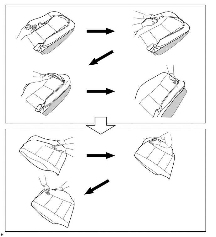
HINT:
- Do not push the pad into the cover. Instead, secure the pad and install the cover to the pad.
- For Seatback Side:
When installing the cover to the outer side, install the cover up until the installation area of the outer side headrest support.
- Do not apply an excessive amount of force when covering the corners, as doing so may cause the cover to tear or fray.
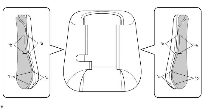
(c) Align the cover seam line with the edges of the pad.
HINT:
- Double-stitch type:
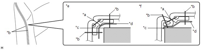
*a
Cover Seam Line
*b
Cover Seam (Stitch)
*c
Pad Edge
*d
Felt
*e
Correct
*f
Incorrect
- Single-stitch type:
Align the seam allowance in a single direction.
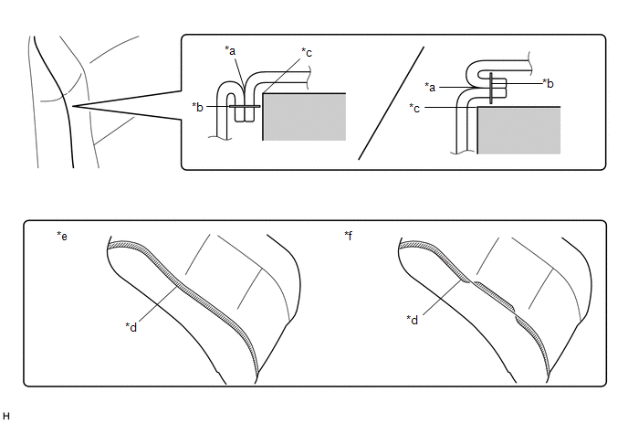
*a
Cover Seam Line
*b
Cover Seam (Stitch)
*c
Pad Edge
*d
Seam Allowance of Cover
*e
Correct
*f
Incorrect
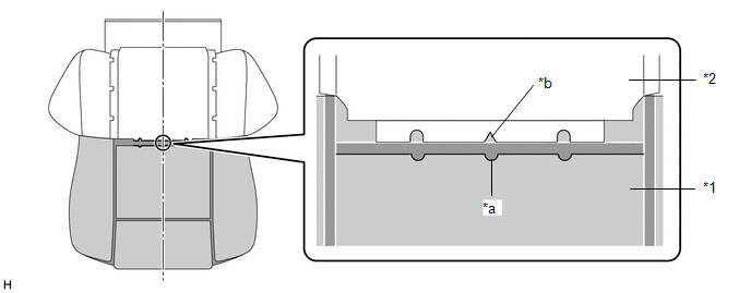
(d) Push the cover seam allowance securely into the groove in the pad.
HINT:
Make sure to completely push the seam allowance into the groove. Wrinkles will form if any of the seam allowance is outside the groove.
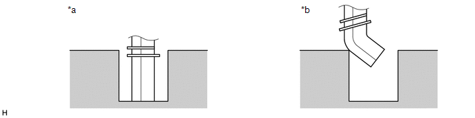
|
*a |
Correct |
*b |
Incorrect |
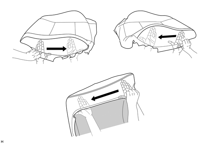
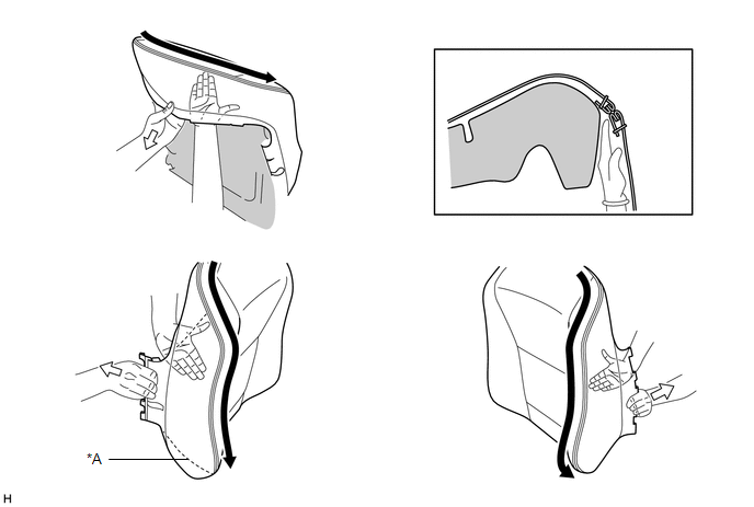
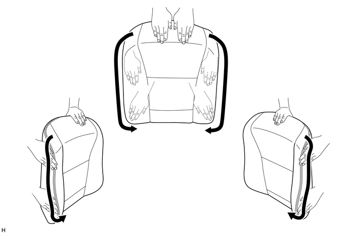
REMOVE WRINKLES
(a) After installing the cover with pad to the seat frame, use your fingers to trace the seam line of each part and remove wrinkles.
NOTICE:
If there are wrinkles in the webbing, wrinkles will appear on the surface of the cover.
|
*A |
w/ Airbag |
- |
- |
CHECKS TO PERFORM AFTER WORK IS FINISHED
(a) Smooth the cover as shown in the illustration and make sure that there are no wrinkles.
HINT:
- If wrinkles remain, it is very likely that the covering was not properly performed.
- If waves form in the seam line, it is very likely that the seam allowance is not in the groove or the position of the felt is incorrect.

 Components
COMPONENTS
ILLUSTRATION
*1
FRONT INNER SEAT TRACK BRACKET COVER
*2
FRONT OUTER SEAT TRACK BRACKET COVER
*3
FRONT SEAT ASSEMB ...
Other materials:
Toyota CH-R Service Manual > Audio And Visual System(for Radio And Display Type): Display does not Dim when Light Control Switch is Turned ON
CAUTION / NOTICE / HINT
NOTICE:
Depending on the parts that are replaced during vehicle inspection or
maintenance, performing initialization, registration or calibration may
be needed. Refer to Precaution for Audio and Visual System.
Click here
When replacing the ...
Toyota CH-R Service Manual > Occupant Classification System: Terminals Of Ecu
TERMINALS OF ECU
OCCUPANT DETECTION ECU
Terminal No. (Symbol)
Wiring Color
Terminal Description
Condition
Specified Condition
Y5-1 (SVC1) - Y5-5 (SGD1)
R - G
Front in weight detection sensor sub-assembl ...
Toyota C-HR (AX20) 2023-2026 Owner's Manual
Toyota CH-R Owners Manual
- For safety and security
- Instrument cluster
- Operation of each component
- Driving
- Interior features
- Maintenance and care
- When trouble arises
- Vehicle specifications
- For owners
Toyota CH-R Service Manual
- Introduction
- Maintenance
- Audio / Video
- Cellular Communication
- Navigation / Multi Info Display
- Park Assist / Monitoring
- Brake (front)
- Brake (rear)
- Brake Control / Dynamic Control Systems
- Brake System (other)
- Parking Brake
- Axle And Differential
- Drive Shaft / Propeller Shaft
- K114 Cvt
- 3zr-fae Battery / Charging
- Networking
- Power Distribution
- Power Assist Systems
- Steering Column
- Steering Gear / Linkage
- Alignment / Handling Diagnosis
- Front Suspension
- Rear Suspension
- Tire / Wheel
- Tire Pressure Monitoring
- Door / Hatch
- Exterior Panels / Trim
- Horn
- Lighting (ext)
- Mirror (ext)
- Window / Glass
- Wiper / Washer
- Door Lock
- Heating / Air Conditioning
- Interior Panels / Trim
- Lighting (int)
- Meter / Gauge / Display
- Mirror (int)
- Power Outlets (int)
- Pre-collision
- Seat
- Seat Belt
- Supplemental Restraint Systems
- Theft Deterrent / Keyless Entry

0.0072