Toyota CH-R Service Manual: Stop Light Relay Circuit (C1A4B)
DESCRIPTION
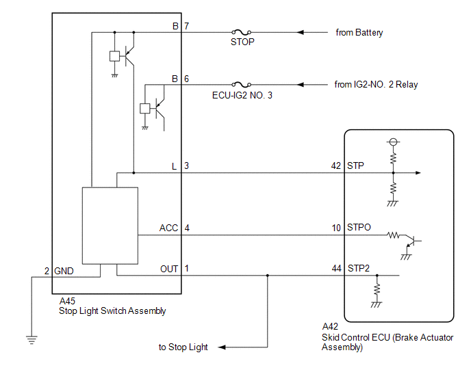
The skid control ECU (brake actuator assembly) sends a stop light operation request signal to the stop light switch assembly. If the skid control ECU (brake actuator assembly) detects a malfunction in the stop light switch assembly circuit, the millimeter wave radar sensor assembly stores DTC C1A4B.
|
DTC No. |
Detection Item |
DTC Detection Condition |
Trouble Area |
|---|---|---|---|
|
C1A4B |
Stop Light Relay Circuit |
Diagnosis condition:
Malfunction condition: Either of the following conditions is met:
|
|
|
Vehicle Condition |
|||
|---|---|---|---|
|
Pattern 1 |
Pattern 2 |
||
|
Diagnosis Condition |
Ignition switch to ON and battery voltage between 11 and 14 V. |
○ |
○ |
|
Malfunction Status |
When the stop light illumination output (STPO) signal is on, a signal has not been input to the STP2 terminal. |
○ |
- |
|
When the stop light illumination output (STPO) signal is off, signals input to the STP terminal and STP2 terminal of the skid control ECU (brake actuator assembly). |
- |
○ |
|
|
Detection Time |
0.3 seconds |
0.3 seconds |
|
|
Number of Trips |
1 trip |
1 trip |
|
HINT:
DTC will be output when conditions for either of the patterns in the table above are met.
WIRING DIAGRAM
CAUTION / NOTICE / HINT
NOTICE:
- The pre-collision system uses the CAN communication system. First, confirm
that there are no malfunctions in the CAN communication system. Refer to
How to Proceed with Troubleshooting.
Click here
.gif)
- Inspect the fuses for circuits related to this system before performing the following inspection procedure.
PROCEDURE
|
1. |
CHECK FOR DTCs (VEHICLE STABILITY CONTROL SYSTEM) |
HINT:
Pre-collision system DTC C1A4B may be stored due to a malfunction in the VSC system. Therefore, it is necessary to check for and troubleshoot VSC system DTCs first.
(a) Check for DTCs.
Click here
|
Result |
Proceed to |
|---|---|
|
Vehicle stability control system DTCs are not output |
A |
|
Vehicle stability control system DTCs are output |
B |
| B | .gif) |
GO TO VEHICLE STABILITY CONTROL SYSTEM |
|
.gif)
|
2. |
CHECK FOR DTCs (PRE-COLLISION SYSTEM) |
(a) Clear the DTCs.
Click here
(b) Make sure that the DTC detection conditions are met.
HINT:
If the detection conditions are not met, the system cannot detect the malfunction.
(c) Check for DTCs.
Click here
|
Result |
Proceed to |
|---|---|
|
DTC C1A4B is output |
A |
|
DTC C1A4B is not output |
B |
| B | |
USE SIMULATION METHOD TO CHECK |
|
|
3. |
REPLACE MILLIMETER WAVE RADAR SENSOR ASSEMBLY |
(a) Replace the millimeter wave radar sensor assembly.
Click here
(b) Adjust the millimeter wave radar sensor assembly.
Click here
|
|
4. |
CHECK FOR DTCs (PRE-COLLISION SYSTEM) |
HINT:
After performing the radar sensor beam axis adjustment, if the same DTC is output again after the DTC detection conditions are met, replace the millimeter wave radar sensor assembly.
(a) Clear the DTCs.
Click here
(b) Make sure that the DTC detection conditions are met.
HINT:
If the detection conditions are not met, the system cannot detect the malfunction.
(c) Check for DTCs.
Click here
|
Result |
Proceed to |
|---|---|
|
DTC C1A4B is not output |
A |
|
DTC C1A4B is output |
B |
| A | |
END (MILLIMETER WAVE RADAR SENSOR ASSEMBLY WAS DEFECTIVE) |
| B | |
REPLACE SKID CONTROL ECU (BRAKE ACTUATOR ASSEMBLY) |
 Skid Control Buzzer Circuit (C1A4A)
DESCRIPTION
The millimeter wave radar sensor assembly is connected to the forward recognition
camera via CAN communication.
The millimeter wave radar sensor assembly operates the pre-collision ala ...
 Steering Angle Sensor (C1A47)
DESCRIPTION
The millimeter wave radar sensor assembly receives steering angle information
from the steering angle sensor (spiral cable with sensor sub-assembly). If the millimeter
wave radar sens ...
Other materials:
Toyota CH-R Service Manual > Audio And Visual System(for Radio Receiver Type): Registered Device cannot be Deleted
PROCEDURE
1.
DELETE OPERATION
(a) Check if a registered portable player can be deleted normally.
OK:
Registered portable player can be deleted normally.
OK
END
NG
PROCEED TO NEXT SUSPECTED AREA SHOWN IN PROBLEM SYM ...
Toyota CH-R Service Manual > Windshield Deicer System: Data List / Active Test
DATA LIST / ACTIVE TEST
ACTIVE TEST
HINT:
Using the Techstream to perform Active Tests allows relays, VSVs, actuators and
other items to be operated without removing any parts. This non-intrusive functional
inspection can be very useful because intermittent operation may be discovered before ...
Toyota C-HR (AX20) 2023-2026 Owner's Manual
Toyota CH-R Owners Manual
- For safety and security
- Instrument cluster
- Operation of each component
- Driving
- Interior features
- Maintenance and care
- When trouble arises
- Vehicle specifications
- For owners
Toyota CH-R Service Manual
- Introduction
- Maintenance
- Audio / Video
- Cellular Communication
- Navigation / Multi Info Display
- Park Assist / Monitoring
- Brake (front)
- Brake (rear)
- Brake Control / Dynamic Control Systems
- Brake System (other)
- Parking Brake
- Axle And Differential
- Drive Shaft / Propeller Shaft
- K114 Cvt
- 3zr-fae Battery / Charging
- Networking
- Power Distribution
- Power Assist Systems
- Steering Column
- Steering Gear / Linkage
- Alignment / Handling Diagnosis
- Front Suspension
- Rear Suspension
- Tire / Wheel
- Tire Pressure Monitoring
- Door / Hatch
- Exterior Panels / Trim
- Horn
- Lighting (ext)
- Mirror (ext)
- Window / Glass
- Wiper / Washer
- Door Lock
- Heating / Air Conditioning
- Interior Panels / Trim
- Lighting (int)
- Meter / Gauge / Display
- Mirror (int)
- Power Outlets (int)
- Pre-collision
- Seat
- Seat Belt
- Supplemental Restraint Systems
- Theft Deterrent / Keyless Entry

0.0086