Toyota CH-R Service Manual: Skid Control Buzzer Circuit (C1A4A)
DESCRIPTION
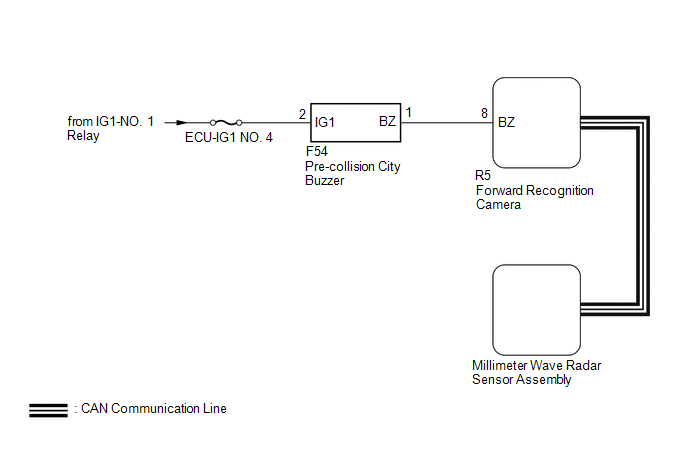
The millimeter wave radar sensor assembly is connected to the forward recognition camera via CAN communication.
The millimeter wave radar sensor assembly operates the pre-collision alarm by sending a buzzer request signal to the pre-collision city buzzer.
If the millimeter wave radar sensor assembly detects a malfunction in the pre-collision city buzzer circuit, it stores DTC C1A4A.
|
DTC No. |
Detection Item |
DTC Detection Condition |
Trouble Area |
|---|---|---|---|
|
C1A4A |
Skid Control Buzzer Circuit |
When the ignition switch is ON and the pre-collision alarm is operating, either of the following conditions is met:
|
|
|
Vehicle Condition |
|||
|---|---|---|---|
|
Pattern 1 |
Pattern 2 |
||
|
Diagnosis Condition |
When the ignition switch is ON and the pre-collision alarm is operating. |
○ |
○ |
|
Malfunction Status |
A buzzer request signal is sent to the pre-collision city buzzer but the buzzer does not sound. |
○ |
- |
|
A buzzer request signal is not sent to the pre-collision city buzzer but the buzzer sounds. |
- |
○ |
|
|
Detection Time |
0.3 seconds |
0.3 seconds |
|
|
Number of Trips |
1 trip |
1 trip |
|
HINT:
DTC will be output when conditions for either of the patterns in the table above are met.
WIRING DIAGRAM
CAUTION / NOTICE / HINT
NOTICE:
- Inspect the fuses for circuits related to this system before performing the following procedure.
- When replacing the millimeter wave radar sensor assembly, always replace it with a new one.
- When the millimeter wave radar sensor assembly is replaced with a new
one, adjustment of the radar sensor beam axis must be performed.
Click here
.gif)
- If the forward recognition camera has been replaced with a new one,
be sure to perform forward recognition axis adjustment.
Click here
- When a malfunction occurs in the communication line to the forward recognition
camera, U023A and/or U1002 is output. If a DTC related to the CAN communication
line is output, first troubleshoot the CAN communication line.
Click here
PROCEDURE
|
1. |
CHECK FOR DTCs (PRE-COLLISION SYSTEM) |
(a) Clear the DTCs.
Click here
(b) Perform the Active Test according to the display on the Techstream.
Click here
NOTICE:
Perform the Active Test for 1 second or more.
HINT:
Performing the Active Test for 1 second or more causes DTC C1A4A to be stored if the DTC detection conditions are met.
Body Electrical > Pre-Collision 2 > Active Test|
Tester Display |
Measurement Item |
Control Range |
Diagnostic Note |
|---|---|---|---|
|
PCS Collision Alarm Buzzer |
Pre-collision city buzzer |
ON / OFF |
Test possible with ignition switch to ON Vehicle condition: Vehicle stopped |
|
Tester Display |
|---|
|
PCS Collision Alarm Buzzer |
(c) Check for DTCs.
Click here
|
Result |
Proceed to |
|---|---|
|
DTC C1A4A is not output |
A |
|
DTC C1A4A is output |
B |
| A | .gif) |
USE SIMULATION METHOD TO CHECK |
|
.gif)
|
2. |
CHECK TERMINAL VOLTAGE |
|
(a) Disconnect the pre-collision city buzzer connector. |
|
(b) Measure the voltage according to the value(s) in the table below.
Standard Voltage:
|
Tester Connection |
Switch Condition |
Specified Condition |
|---|---|---|
|
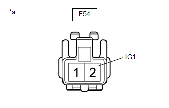
F54-2 (IG1) - Body ground |
Ignition switch ON |
11 to 14 V |
|
Ignition switch off |
Below 1 V |
(c) Connect the F54 pre-collision city buzzer connector.
| NG | |
REPAIR OR REPLACE HARNESS OR CONNECTOR (PRE-COLLISION CITY BUZZER - BATTERY) |
|
|
3. |
CHECK HARNESS AND CONNECTOR (PRE-COLLISION CITY BUZZER - FORWARD RECOGNITION CAMERA) |
(a) Disconnect the F54 pre-collision city buzzer connector.
(b) Disconnect the R5 forward recognition camera connector.
(c) Measure the resistance according to the value(s) in the table below.
Standard Resistance:
|
Tester Connection |
Condition |
Specified Condition |
|---|---|---|
|
F54-1 (BZ) - R5-8 (BZ) |
Always |
Below 1 Ω |
|
F54-1 (BZ) or R5-8 (BZ) - Body ground |
Always |
10 kΩ or higher |
(d) Connect the R5 forward recognition camera connector.
(e) Connect the F54 pre-collision city buzzer connector.
| OK | |
GO TO STEP 6 |
|
|
4. |
REPAIR OR REPLACE HARNESS OR CONNECTOR (PRE-COLLISION CITY BUZZER - FORWARD RECOGNITION CAMERA) |
(a) Repair or replace the harness or connector.
|
|
5. |
CHECK FOR DTCs (PRE-COLLISION SYSTEM) |
(a) Clear the DTCs.
Click here
(b) Perform the Active Test according to the display on the Techstream.
Click here
NOTICE:
Perform the Active Test for 1 second or more.
HINT:
Performing the Active Test for 1 second or more causes DTC C1A4A to be stored if the DTC detection conditions are met.
Body Electrical > Pre-Collision 2 > Active Test|
Tester Display |
Measurement Item |
Control Range |
Diagnostic Note |
|---|---|---|---|
|
PCS Collision Alarm Buzzer |
Pre-collision city buzzer |
ON / OFF |
Test possible with ignition switch to ON Vehicle condition: Vehicle stopped |
|
Tester Display |
|---|
|
PCS Collision Alarm Buzzer |
(c) Check for DTCs.
Click here
|
Result |
Proceed to |
|---|---|
|
DTC C1A4A is not output |
A |
|
DTC C1A4A is output |
B |
| A | |
END |
|
|
6. |
INSPECT PRE-COLLISION CITY BUZZER (CONFIRM BUZZER OPERATION) |
(a) Turn the ignition switch to ON.
(b) Check if the pre-collision city buzzer is sounding.
|
Result |
Proceed to |
|---|---|
|
The pre-collision city buzzer does not sound when the ignition switch is ON |
A |
|
The pre-collision city buzzer sounds continuously when the ignition switch is ON |
B |
| B | |
GO TO STEP 8 |
|
|
7. |
INSPECT PRE-COLLISION CITY BUZZER (UNIT INSPECTION) |
(a) Remove the pre-collision city buzzer.
Click here
(b) Inspect the pre-collision city buzzer.
Click here
|
Result |
Proceed to |
|---|---|
|
Pre-collision city buzzer is abnormal |
A |
|
Pre-collision city buzzer is normal |
B |
| B | |
GO TO STEP 9 |
|
|
8. |
REPLACE PRE-COLLISION CITY BUZZER |
(a) Replace the pre-collision city buzzer.
Click here
|
|
9. |
CHECK FOR DTCs (PRE-COLLISION SYSTEM) |
(a) Clear the DTCs.
Click here
(b) Perform the Active Test according to the display on the Techstream.
Click here
NOTICE:
Perform the Active Test for 1 second or more.
HINT:
Performing the Active Test for 1 second or more causes DTC C1A4A to be stored if the DTC detection conditions are met.
Body Electrical > Pre-Collision 2 > Active Test|
Tester Display |
Measurement Item |
Control Range |
Diagnostic Note |
|---|---|---|---|
|
PCS Collision Alarm Buzzer |
Pre-collision city buzzer |
ON / OFF |
Test possible with ignition switch to ON Vehicle condition: Vehicle stopped |
|
Tester Display |
|---|
|
PCS Collision Alarm Buzzer |
(c) Check for DTCs.
Click here
|
Result |
Proceed to |
|---|---|
|
DTC C1A4A is not output |
A |
|
DTC C1A4A is output |
B |
| A | |
END |
|
|
10. |
REPLACE FORWARD RECOGNITION CAMERA |
(a) Replace the forward recognition camera.
Click here
(b) Perform forward recognition axis adjustment.
Click here
|
|
11. |
CHECK FOR DTCs (PRE-COLLISION SYSTEM) |
(a) Clear the DTCs.
Click here
(b) Perform the Active Test according to the display on the Techstream.
Click here
NOTICE:
Perform the Active Test for 1 second or more.
HINT:
Performing the Active Test for 1 second or more causes DTC C1A4A to be stored if the DTC detection conditions are met.
Body Electrical > Pre-Collision 2 > Active Test|
Tester Display |
Measurement Item |
Control Range |
Diagnostic Note |
|---|---|---|---|
|
PCS Collision Alarm Buzzer |
Pre-collision city buzzer |
ON / OFF |
Test possible with ignition switch to ON Vehicle condition: Vehicle stopped |
|
Tester Display |
|---|
|
PCS Collision Alarm Buzzer |
(c) Check for DTCs.
Click here
|
Result |
Proceed to |
|---|---|
|
DTC C1A4A is not output |
A |
|
DTC C1A4A is output |
B |
| A | |
END (FORWARD RECOGNITION CAMERA WAS DEFECTIVE) |
|
|
12. |
REPLACE MILLIMETER WAVE RADAR SENSOR ASSEMBLY |
(a) Replace the millimeter wave radar sensor assembly.
Click here
(b) Adjust the millimeter wave radar sensor assembly.
Click here
|
|
13. |
CLEAR DTC (PRE-COLLISION SYSTEM) |
(a) Clear the DTCs.
Click here
| NEXT | |
END (MILLIMETER WAVE RADAR SENSOR ASSEMBLY WAS DEFECTIVE) |
 Brake System Malfunction (C1A50)
DESCRIPTION
When the pre-collision system is operating, the millimeter wave radar sensor
assembly sends brake control signals to the skid control ECU (brake actuator assembly).
When the millimeter ...
 Stop Light Relay Circuit (C1A4B)
DESCRIPTION
The skid control ECU (brake actuator assembly) sends a stop light operation request
signal to the stop light switch assembly. If the skid control ECU (brake actuator
assembly) detects ...
Other materials:
Toyota CH-R Service Manual > Shift Lever: Inspection
INSPECTION
PROCEDURE
1. INSPECT SHIFT LOCK CONTROL UNIT ASSEMBLY (w/o Smart Key System)
HINT:
If the results of the following inspections are as specified but a malfunction
has occurred, replace the shift lock control unit assembly.
(a) Inspect the wire harness.
(1) Disconnect the ...
Toyota CH-R Service Manual > Rear Brake(for Tmc Made): Installation
INSTALLATION
CAUTION / NOTICE / HINT
HINT:
Use the same procedure for the RH side and LH side.
The following procedure is for the LH side.
PROCEDURE
1. INSTALL REAR DISC
(a) Align the matchmarks of the rear disc and rear axle hub and bearing
assembly, and insta ...
Toyota C-HR (AX20) 2023-2026 Owner's Manual
Toyota CH-R Owners Manual
- For safety and security
- Instrument cluster
- Operation of each component
- Driving
- Interior features
- Maintenance and care
- When trouble arises
- Vehicle specifications
- For owners
Toyota CH-R Service Manual
- Introduction
- Maintenance
- Audio / Video
- Cellular Communication
- Navigation / Multi Info Display
- Park Assist / Monitoring
- Brake (front)
- Brake (rear)
- Brake Control / Dynamic Control Systems
- Brake System (other)
- Parking Brake
- Axle And Differential
- Drive Shaft / Propeller Shaft
- K114 Cvt
- 3zr-fae Battery / Charging
- Networking
- Power Distribution
- Power Assist Systems
- Steering Column
- Steering Gear / Linkage
- Alignment / Handling Diagnosis
- Front Suspension
- Rear Suspension
- Tire / Wheel
- Tire Pressure Monitoring
- Door / Hatch
- Exterior Panels / Trim
- Horn
- Lighting (ext)
- Mirror (ext)
- Window / Glass
- Wiper / Washer
- Door Lock
- Heating / Air Conditioning
- Interior Panels / Trim
- Lighting (int)
- Meter / Gauge / Display
- Mirror (int)
- Power Outlets (int)
- Pre-collision
- Seat
- Seat Belt
- Supplemental Restraint Systems
- Theft Deterrent / Keyless Entry

0.0098