Toyota CH-R Service Manual: Lost Communication with Gateway Module (U1002)
DESCRIPTION
|
DTC No. |
Detection Item |
DTC Detection Condition |
Trouble Area |
|---|---|---|---|
|
U1002 |
Lost Communication with Gateway Module |
When the ignition switch is ON, a communication error between the forward recognition camera and millimeter wave radar sensor assembly is detected for approximately 0.3 seconds. |
|
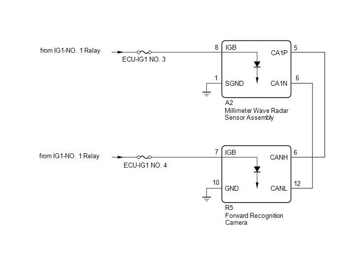
WIRING DIAGRAM
CAUTION / NOTICE / HINT
NOTICE:
- Inspect the fuses for circuits related to this system before performing the following inspection procedure.
- Before measuring the resistance of the CAN bus, turn the ignition switch off and leave the vehicle for 1 minute or more without operating the key or any switches, or opening or closing the doors. After that, disconnect the cable from the negative (-) battery terminal and leave the vehicle for 1 minute or more before measuring the resistance.
- After turning the ignition switch off, waiting time may be required
before disconnecting the cable from the negative (-) battery terminal. Therefore,
make sure to read the disconnecting the cable from the negative (-) battery
terminal notices before proceeding with work.
Click here
.gif)
- If the forward recognition camera has been replaced with a new one,
be sure to perform forward recognition axis adjustment.
Click here
- When the millimeter wave radar sensor assembly is replaced with a new one, adjustment of the radar sensor beam axis must be performed.
HINT:
- Operating the ignition switch, any other switches or a door triggers related ECUs and sensors to communicate using the CAN communication system. This communication will cause the resistance value to change.
- Even after DTCs are cleared, if a DTC is stored again after driving the vehicle for a while, the malfunction may be occurring due to vibration of the vehicle. In such a case, wiggling the connectors of ECUs or wire harnesses while performing the inspection below may help determine the cause of the malfunction.
PROCEDURE
|
1. |
CHECK FOR DTCs (PRE-COLLISION SYSTEM) |
(a) Check for DTCs.
Click here
|
Result |
Proceed to |
|---|---|
|
DTC U023A and/or U1002 and other DTCs are output |
A |
|
Only DTC U023A and/or U1002 is output |
B |
| A | .gif) |
GO TO DIAGNOSTIC TROUBLE CODE CHART |
|
.gif)
|
2. |
CHECK FOR OPEN IN CAN BUS SUB LINES (FORWARD RECOGNITION CAMERA) |
(a) Disconnect the cable from the negative (-) battery terminal.
|
(b) Disconnect the forward recognition camera connector. |
|

(c) Measure the resistance according to the value(s) in the table below.
Standard Resistance:
|
Tester Connection |
Condition |
Specified Condition |
|---|---|---|
|
R5-6 (CANH) - R5-12 (CANL) |
Cable disconnected from negative (-) battery terminal |
108 to 132 Ω |
(d) Connect the forward recognition camera connector.
| NG | |
REPAIR OR REPLACE CAN BUS SUB LINE OR CONNECTOR (FORWARD RECOGNITION CAMERA - MILLIMETER WAVE RADAR SENSOR ASSEMBLY) |
|
|
3. |
CHECK HARNESS AND CONNECTOR (POWER SOURCE VOLTAGE (FORWARD RECOGNITION CAMERA)) |
|
(a) Disconnect the forward recognition camera connector. |
|
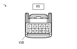
(b) Connect the cable to the negative (-) battery terminal.
(c) Measure the voltage according to the value(s) in the table below.
Standard Voltage:
|
Tester Connection |
Switch Condition |
Specified Condition |
|---|---|---|
|
R5-7 (IGB) - Body ground |
Ignition switch ON |
11 to 14 V |
(d) Connect the forward recognition camera connector.
| NG | |
REPAIR OR REPLACE HARNESS OR CONNECTOR (POWER SOURCE CIRCUIT) |
|
|
4. |
CHECK HARNESS AND CONNECTOR (FORWARD RECOGNITION CAMERA - BODY GROUND) |
|
(a) Disconnect the forward recognition camera connector. |
|
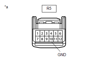
(b) Measure the resistance according to the value(s) in the table below.
Standard Resistance:
|
Tester Connection |
Condition |
Specified Condition |
|---|---|---|
|
R5-10 (GND) - Body ground |
Always |
Below 1 Ω |
(c) Connect the forward recognition camera connector.
| NG | |
REPAIR OR REPLACE HARNESS OR CONNECTOR |
|
|
5. |
CHECK HARNESS AND CONNECTOR (POWER SOURCE VOLTAGE (MILLIMETER WAVE RADAR SENSOR ASSEMBLY)) |
|
(a) Disconnect the millimeter wave radar sensor assembly connector. |
|
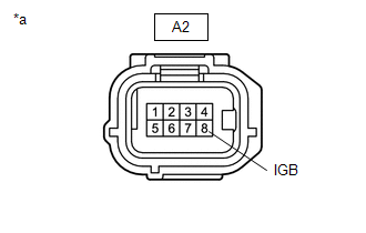
(b) Measure the voltage according to the value(s) in the table below.
Standard Voltage:
|
Tester Connection |
Switch Condition |
Specified Condition |
|---|---|---|
|
A2-8 (IGB) - Body ground |
Ignition switch ON |
11 to 14 V |
(c) Connect the millimeter wave radar sensor assembly connector.
| NG | |
REPAIR OR REPLACE HARNESS OR CONNECTOR (POWER SOURCE CIRCUIT) |
|
|
6. |
CHECK HARNESS AND CONNECTOR (MILLIMETER WAVE RADAR SENSOR ASSEMBLY - BODY GROUND) |
|
(a) Disconnect the millimeter wave radar sensor assembly connector. |
|
(b) Measure the resistance according to the value(s) in the table below.
Standard Resistance:
|
Tester Connection |
Condition |
Specified Condition |
|---|---|---|
|
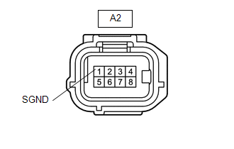
A2-1 (SGND) - Body ground |
Always |
Below 1 Ω |
(c) Connect the millimeter wave radar sensor assembly connector.
| NG | |
REPAIR OR REPLACE HARNESS OR CONNECTOR |
|
|
7. |
REPLACE FORWARD RECOGNITION CAMERA |
(a) Replace the forward recognition camera.
Click here
(b) Perform forward recognition axis adjustment.
Click here
|
|
8. |
CHECK FOR DTCs (PRE-COLLISION SYSTEM) |
(a) Clear the DTCs.
Click here
(b) Make sure that the DTC detection conditions are met.
HINT:
If the detection conditions are not met, the system cannot detect the malfunction.
(c) Check for DTCs.
Click here
|
Result |
Proceed to |
|---|---|
|
DTC U023A is not output |
A |
|
DTC U023A is output |
B |
| A | |
END (FORWARD RECOGNITION CAMERA WAS DEFECTIVE) |
|
|
9. |
REPLACE MILLIMETER WAVE RADAR SENSOR ASSEMBLY |
(a) Replace the millimeter wave radar sensor assembly.
Click here
(b) Adjust the millimeter wave radar sensor assembly.
Click here
|
|
10. |
CLEAR DTC (PRE-COLLISION SYSTEM) |
(a) Clear the DTCs.
Click here
| NEXT | |
END (MILLIMETER WAVE RADAR SENSOR ASSEMBLY WAS DEFECTIVE) |
 Lost Communication with Cruise Control Front Distance Range Sensor (U0235)
DESCRIPTION
The millimeter wave radar sensor assembly is connected to the skid control ECU
(brake actuator assembly) by a CAN communication line.
When entering test mode, the skid control ECU (bra ...
 Lost Communication with ECM / PCM "A" (U0100,U0125,U0126,U0129,U023A)
DESCRIPTION
These DTCs are stored when a communication malfunction occurs between ECUs that
perform pre-collision control.
DTC No.
Detection Item
DTC Detection Con ...
Other materials:
Toyota CH-R Service Manual > Brake Master Cylinder: Disassembly
DISASSEMBLY
PROCEDURE
1. REMOVE BRAKE MASTER CYLINDER RESERVOIR ASSEMBLY
(a) Mount the brake master cylinder sub-assembly in a vise.
NOTICE:
Place aluminum plates on the vise to prevent damage to the brake master cylinder
sub-assembly.
(b) Using an T20 "TORX" socket wren ...
Toyota CH-R Service Manual > Audio And Visual System(for Radio And Display Type): Portable Player cannot be Connected Manually/Automatically
CAUTION / NOTICE / HINT
HINT:
Some versions of "Bluetooth" compatible audio players may not function properly,
or the functions may be limited using the radio and display receiver assembly, even
if the portable audio player itself can play files.
Click here
PROCEDURE
...
Toyota C-HR (AX20) 2023-2026 Owner's Manual
Toyota CH-R Owners Manual
- For safety and security
- Instrument cluster
- Operation of each component
- Driving
- Interior features
- Maintenance and care
- When trouble arises
- Vehicle specifications
- For owners
Toyota CH-R Service Manual
- Introduction
- Maintenance
- Audio / Video
- Cellular Communication
- Navigation / Multi Info Display
- Park Assist / Monitoring
- Brake (front)
- Brake (rear)
- Brake Control / Dynamic Control Systems
- Brake System (other)
- Parking Brake
- Axle And Differential
- Drive Shaft / Propeller Shaft
- K114 Cvt
- 3zr-fae Battery / Charging
- Networking
- Power Distribution
- Power Assist Systems
- Steering Column
- Steering Gear / Linkage
- Alignment / Handling Diagnosis
- Front Suspension
- Rear Suspension
- Tire / Wheel
- Tire Pressure Monitoring
- Door / Hatch
- Exterior Panels / Trim
- Horn
- Lighting (ext)
- Mirror (ext)
- Window / Glass
- Wiper / Washer
- Door Lock
- Heating / Air Conditioning
- Interior Panels / Trim
- Lighting (int)
- Meter / Gauge / Display
- Mirror (int)
- Power Outlets (int)
- Pre-collision
- Seat
- Seat Belt
- Supplemental Restraint Systems
- Theft Deterrent / Keyless Entry

0.0068