Toyota CH-R Service Manual: Engine Oil Pressure Switch Circuit
DESCRIPTION
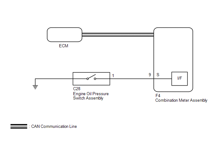
The combination meter assembly and engine oil pressure switch assembly are connected via direct line. The combination meter assembly determines the engine oil pressure based on the engine oil pressure switch ON/OFF signal.
HINT:
- The combination meter assembly receives various vehicle information signals from the ECM via CAN communication in order to output warnings.
- The combination meter assembly operates the following to output oil
pressure warnings:
- Engine oil pressure warning light
- Engine oil pressure warning buzzer
- Engine oil pressure warning message on multi-information display
WIRING DIAGRAM
CAUTION / NOTICE / HINT
NOTICE:
- The following troubleshooting procedure is based on the assumption that
the ECM is normal. Confirm that the SFI system is not malfunctioning before
performing the following procedure.
- w/ Canister Pump Module:
Click here
.gif)
- w/o Canister Pump Module:
Click here
- w/ Canister Pump Module:
- When replacing the combination meter assembly, always replace it with a new one. If a combination meter assembly which was installed to another vehicle is used, the information stored in it will not match the information from the vehicle and a DTC may be stored.
PROCEDURE
|
1. |
INSPECT ENGINE OIL PRESSURE SWITCH ASSEMBLY |
(a) Remove the engine oil pressure switch assembly.
Click here
(b) Inspect the engine oil pressure switch assembly.
Click here
| NG | .gif) |
REPLACE ENGINE OIL PRESSURE SWITCH ASSEMBLY |
|
.gif)
|
2. |
CHECK HARNESS AND CONNECTOR (ENGINE OIL PRESSURE SWITCH ASSEMBLY - COMBINATION METER ASSEMBLY) |
(a) Disconnect the F4 combination meter assembly connector.
(b) Measure the resistance according to the value(s) in the table below.
Standard Resistance:
|
Tester Connection |
Condition |
Specified Condition |
|---|---|---|
|
F4-9 (S) - C28-1 |
Always |
Below 1 Ω |
|
F4-9 (S) - Body ground |
Always |
10 kΩ or higher |
| OK | |
REPLACE COMBINATION METER ASSEMBLY |
| NG | |
REPAIR OR REPLACE HARNESS OR CONNECTOR |
 Meter Illumination is Always Dark
DESCRIPTION
The combination meter assembly receives signals from this circuit to adjust the
illumination of the combination meter assembly. The combination meter assembly sets
the illumination le ...
 Steering Pad Switch Circuit
DESCRIPTION
The combination meter assembly and steering pad switch assembly are connected
via direct line. The main display and multi-information display in the combination
meter assembly are ope ...
Other materials:
Toyota CH-R Service Manual > Steering Gear: Installation
INSTALLATION
PROCEDURE
1. INSTALL TIE ROD END SUB-ASSEMBLY LH
(a) Install the lock nut and tie rod end sub-assembly LH to the steering
gear assembly until the matchmarks are aligned.
HINT:
After adjusting the toe-in, tighten the lock nut.
...
Toyota CH-R Service Manual > Toyota Entune System: How To Proceed With Troubleshooting
CAUTION / NOTICE / HINT
HINT:
Use the following procedure to troubleshoot the Entune system.
*: Use the Techstream.
PROCEDURE
1.
VEHICLE BROUGHT TO WORKSHOP
NEXT
2.
...
Toyota C-HR (AX20) 2023-2026 Owner's Manual
Toyota CH-R Owners Manual
- For safety and security
- Instrument cluster
- Operation of each component
- Driving
- Interior features
- Maintenance and care
- When trouble arises
- Vehicle specifications
- For owners
Toyota CH-R Service Manual
- Introduction
- Maintenance
- Audio / Video
- Cellular Communication
- Navigation / Multi Info Display
- Park Assist / Monitoring
- Brake (front)
- Brake (rear)
- Brake Control / Dynamic Control Systems
- Brake System (other)
- Parking Brake
- Axle And Differential
- Drive Shaft / Propeller Shaft
- K114 Cvt
- 3zr-fae Battery / Charging
- Networking
- Power Distribution
- Power Assist Systems
- Steering Column
- Steering Gear / Linkage
- Alignment / Handling Diagnosis
- Front Suspension
- Rear Suspension
- Tire / Wheel
- Tire Pressure Monitoring
- Door / Hatch
- Exterior Panels / Trim
- Horn
- Lighting (ext)
- Mirror (ext)
- Window / Glass
- Wiper / Washer
- Door Lock
- Heating / Air Conditioning
- Interior Panels / Trim
- Lighting (int)
- Meter / Gauge / Display
- Mirror (int)
- Power Outlets (int)
- Pre-collision
- Seat
- Seat Belt
- Supplemental Restraint Systems
- Theft Deterrent / Keyless Entry

0.0066