Toyota CH-R Service Manual: Light Control Rheostat
Components
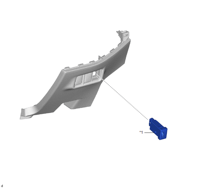
COMPONENTS
ILLUSTRATION
|
*1 |
LIGHT CONTROL RHEOSTAT |
- |
- |
Removal
REMOVAL
PROCEDURE
1. REMOVE FUSE BOX OPENING COVER
Click here .gif)
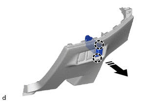
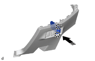
2. REMOVE LIGHT CONTROL RHEOSTAT
(a) Disengage the claws to remove the light control rheostat as shown in the illustration.
.png) |
Remove in this Direction |
Inspection
INSPECTION
PROCEDURE
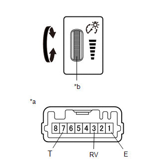
1. INSPECT LIGHT CONTROL RHEOSTAT
|
(a) Inspect the light control rheostat. (1) Measure the resistance according to the value(s) in the table below. Standard Resistance:
If the result is not as specified, replace the light control rheostat. |
|
|
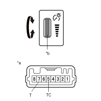
(b) Inspect the TAIL cancel switch. HINT: The TAIL cancel switch is built into the light control rheostat. (1) Measure the resistance according to the value(s) in the table below. Standard Resistance:
If the result is not as specified, replace the light control rheostat. |
|
Installation
INSTALLATION
PROCEDURE
1. INSTALL LIGHT CONTROL RHEOSTAT
(a) Engage the claws to install the light control rheostat as shown in the illustration.
.png) |
Install in this Direction |
2. INSTALL FUSE BOX OPENING COVER
Click here .gif)
 Installation
INSTALLATION
PROCEDURE
1. INSTALL COMBINATION METER ASSEMBLY
(a) Connect the 2 connectors to install the combination meter assembly.
(b) Engage the guides and clips.
...

Other materials:
Toyota CH-R Service Manual > Steering Lock System: Diagnostic Trouble Code Chart
DIAGNOSTIC TROUBLE CODE CHART
Steering Lock System
DTC No.
Detection Item
DTC Detection Condition
Note
Link
B2781
Open / Short in Steering Lock ECU
One of the following conditions is met (1-trip detection ...
Toyota CH-R Owners Manual > Dynamic radar cruise control with full-speed range: Changing the vehicle-to-vehicle distance (vehicle-to-vehicle distance
control mode)
Pressing the switch changes the vehicle-to-vehicle distance as follows:
Long
Medium
Short
The vehicle-to-vehicle distance is set automatically to long mode when the engine
switch is turned to the "ON" position (vehicles without a smart key system) or IGNITION
ON mode (vehicl ...
Toyota C-HR (AX20) 2023-2026 Owner's Manual
Toyota CH-R Owners Manual
- For safety and security
- Instrument cluster
- Operation of each component
- Driving
- Interior features
- Maintenance and care
- When trouble arises
- Vehicle specifications
- For owners
Toyota CH-R Service Manual
- Introduction
- Maintenance
- Audio / Video
- Cellular Communication
- Navigation / Multi Info Display
- Park Assist / Monitoring
- Brake (front)
- Brake (rear)
- Brake Control / Dynamic Control Systems
- Brake System (other)
- Parking Brake
- Axle And Differential
- Drive Shaft / Propeller Shaft
- K114 Cvt
- 3zr-fae Battery / Charging
- Networking
- Power Distribution
- Power Assist Systems
- Steering Column
- Steering Gear / Linkage
- Alignment / Handling Diagnosis
- Front Suspension
- Rear Suspension
- Tire / Wheel
- Tire Pressure Monitoring
- Door / Hatch
- Exterior Panels / Trim
- Horn
- Lighting (ext)
- Mirror (ext)
- Window / Glass
- Wiper / Washer
- Door Lock
- Heating / Air Conditioning
- Interior Panels / Trim
- Lighting (int)
- Meter / Gauge / Display
- Mirror (int)
- Power Outlets (int)
- Pre-collision
- Seat
- Seat Belt
- Supplemental Restraint Systems
- Theft Deterrent / Keyless Entry

0.0092