Toyota CH-R Service Manual: Components
COMPONENTS
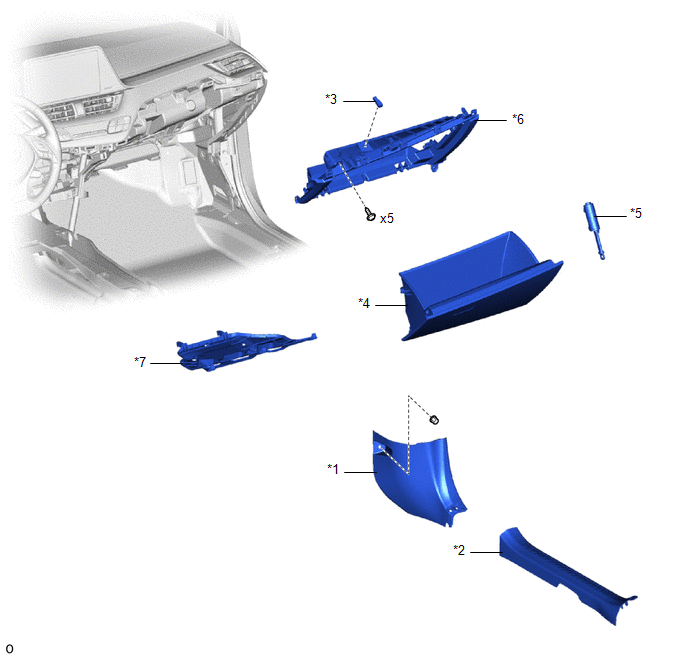
ILLUSTRATION
|
*1 |
COWL SIDE TRIM BOARD RH |
*2 |
FRONT DOOR SCUFF PLATE RH |
|
*3 |
GLOVE BOX LIGHT ASSEMBLY |
*4 |
GLOVE COMPARTMENT DOOR ASSEMBLY |
|
*5 |
GLOVE COMPARTMENT DOOR STOPPER SUB-ASSEMBLY |
*6 |
NO. 2 INSTRUMENT PANEL LOWER FINISH PANEL |
|
*7 |
NO. 2 INSTRUMENT PANEL UNDER COVER SUB-ASSEMBLY |
- |
- |
 Glove Box Light
...
 Removal
REMOVAL
PROCEDURE
1. REMOVE REAR CONSOLE BOX ASSEMBLY
Click here
2. REMOVE FRONT DOOR SCUFF PLATE RH
HINT:
Use the same procedure as for the LH side.
Click here
3. REMOVE COWL SIDE TRI ...
Other materials:
Toyota CH-R Service Manual > Center Airbag Sensor Assembly: Components
COMPONENTS
ILLUSTRATION
*A
w/ Rear Air Duct
-
-
*1
AIRBAG SENSOR ASSEMBLY
*2
REAR NO. 2 AIR DUCT
Tightening torque for "Major areas involving basic vehicle performance
...
Toyota CH-R Service Manual > Smart Key System(for Entry Function): How To Proceed With Troubleshooting
CAUTION / NOTICE / HINT
HINT:
Use these procedures to troubleshoot the smart key system (for Entry
Function).
*: Use the Techstream.
PROCEDURE
1.
VEHICLE BROUGHT TO WORKSHOP
NEXT
...
Toyota C-HR (AX20) 2023-2026 Owner's Manual
Toyota CH-R Owners Manual
- For safety and security
- Instrument cluster
- Operation of each component
- Driving
- Interior features
- Maintenance and care
- When trouble arises
- Vehicle specifications
- For owners
Toyota CH-R Service Manual
- Introduction
- Maintenance
- Audio / Video
- Cellular Communication
- Navigation / Multi Info Display
- Park Assist / Monitoring
- Brake (front)
- Brake (rear)
- Brake Control / Dynamic Control Systems
- Brake System (other)
- Parking Brake
- Axle And Differential
- Drive Shaft / Propeller Shaft
- K114 Cvt
- 3zr-fae Battery / Charging
- Networking
- Power Distribution
- Power Assist Systems
- Steering Column
- Steering Gear / Linkage
- Alignment / Handling Diagnosis
- Front Suspension
- Rear Suspension
- Tire / Wheel
- Tire Pressure Monitoring
- Door / Hatch
- Exterior Panels / Trim
- Horn
- Lighting (ext)
- Mirror (ext)
- Window / Glass
- Wiper / Washer
- Door Lock
- Heating / Air Conditioning
- Interior Panels / Trim
- Lighting (int)
- Meter / Gauge / Display
- Mirror (int)
- Power Outlets (int)
- Pre-collision
- Seat
- Seat Belt
- Supplemental Restraint Systems
- Theft Deterrent / Keyless Entry

0.0445