Toyota CH-R Service Manual: Removal
REMOVAL
CAUTION / NOTICE / HINT
The necessary procedures (adjustment, calibration, initialization, or registration) that must be performed after parts are removed, installed, or replaced during the No. 1 cooler thermistor removal/installation are shown below.
Necessary Procedure After Parts Removed/Installed/Replaced|
Replacement Part or Procedure |
Necessary Procedures |
Effects / Inoperative when not performed |
Link |
|---|---|---|---|
|
Disconnect cable from negative battery terminal |
Memorize steering angle neutral point |
Lane departure alert system (w/ Steering Control) |
|
|
Pre-collision system |
|||
|
Initialize back door lock |
Power door lock control system |
|
|
|
No. 1 air conditioning radiator damper servo sub-assembly |
Initialize servo motor (Air conditioning system) |
DTCs are stored |
|
PROCEDURE
1. REMOVE BLOWER ASSEMBLY
Click here
.gif)
2. REMOVE AIR CONDITIONING HARNESS ASSEMBLY
Click here
3. REMOVE NO. 1 AIR CONDITIONING RADIATOR DAMPER SERVO SUB-ASSEMBLY
Click here
4. REMOVE HEATER PIPE GROMMET
Click here
5. REMOVE HEATER CLAMP
Click here
6. REMOVE HEATER RADIATOR UNIT SUB-ASSEMBLY
Click here
7. REMOVE COOLER EXPANSION VALVE
Click here
8. REMOVE NO. 1 COOLER EVAPORATOR SUB-ASSEMBLY
Click here
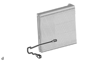
9. REMOVE NO. 1 COOLER THERMISTOR
|
(a) Remove the No. 1 cooler thermistor. |
|
 Components
COMPONENTS
ILLUSTRATION
*1
AIR CONDITIONING HARNESS ASSEMBLY
*2
COOLER EXPANSION VALVE
*3
HEATER CLAMP
*4
...
 Inspection
INSPECTION
PROCEDURE
1. INSPECT NO. 1 COOLER THERMISTOR
(a) Check the resistance.
(1) Measure the resistance according to the value(s) in the table below.
*a
Component wit ...
Other materials:
Toyota CH-R Service Manual > Lighting System: Left Headlight ECU Variation Error (B2456)
DESCRIPTION
This DTC is output when a headlight ECU sub-assembly LH that is incompatible
with the vehicle is installed.
The headlight ECU sub-assembly LH outputs DTC B2456.
DTC No.
Detection Item
DTC Detection Condition
Trouble Area
Note
...
Toyota CH-R Service Manual > Power Window Control System: Operation Check
OPERATION CHECK
CHECK WINDOW LOCK FUNCTION
HINT:
Before performing the window lock switch operation check, make sure that the
window lock switch is off (the switch is not pushed in).
(a) Turn the window lock switch of the multiplex network master switch assembly
on (pushed in) and check th ...
Toyota C-HR (AX20) 2023-2026 Owner's Manual
Toyota CH-R Owners Manual
- For safety and security
- Instrument cluster
- Operation of each component
- Driving
- Interior features
- Maintenance and care
- When trouble arises
- Vehicle specifications
- For owners
Toyota CH-R Service Manual
- Introduction
- Maintenance
- Audio / Video
- Cellular Communication
- Navigation / Multi Info Display
- Park Assist / Monitoring
- Brake (front)
- Brake (rear)
- Brake Control / Dynamic Control Systems
- Brake System (other)
- Parking Brake
- Axle And Differential
- Drive Shaft / Propeller Shaft
- K114 Cvt
- 3zr-fae Battery / Charging
- Networking
- Power Distribution
- Power Assist Systems
- Steering Column
- Steering Gear / Linkage
- Alignment / Handling Diagnosis
- Front Suspension
- Rear Suspension
- Tire / Wheel
- Tire Pressure Monitoring
- Door / Hatch
- Exterior Panels / Trim
- Horn
- Lighting (ext)
- Mirror (ext)
- Window / Glass
- Wiper / Washer
- Door Lock
- Heating / Air Conditioning
- Interior Panels / Trim
- Lighting (int)
- Meter / Gauge / Display
- Mirror (int)
- Power Outlets (int)
- Pre-collision
- Seat
- Seat Belt
- Supplemental Restraint Systems
- Theft Deterrent / Keyless Entry

0.0081