Toyota CH-R Service Manual: Components
COMPONENTS
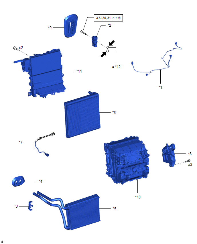
ILLUSTRATION
|
*1 |
AIR CONDITIONING HARNESS ASSEMBLY |
*2 |
COOLER EXPANSION VALVE |
|
*3 |
HEATER CLAMP |
*4 |
HEATER PIPE GROMMET |
|
*5 |
HEATER RADIATOR UNIT SUB-ASSEMBLY |
*6 |
NO. 1 COOLER EVAPORATOR SUB-ASSEMBLY |
|
*7 |
NO. 1 COOLER THERMISTOR |
*8 |
NO. 2 AIR CONDITIONING RADIATOR DAMPER SERVO SUB-ASSEMBLY |
|
*9 |
GROMMET |
*10 |
UPPER HEATER CASE |
|
*11 |
LOWER HEATER CASE |
*12 |
O-RING |
.png) |
N*m (kgf*cm, ft.*lbf): Specified torque |
● |
Non-reusable part |
.png) |
Compressor oil ND-OIL 12 or equivalent |
- |
- |

 Removal
REMOVAL
CAUTION / NOTICE / HINT
The necessary procedures (adjustment, calibration, initialization, or registration)
that must be performed after parts are removed, installed, or replaced during th ...
Other materials:
Toyota CH-R Service Manual > Audio And Visual System(for Radio Receiver Type): Poor Sound Quality in All Modes (Low Volume)
PROCEDURE
1.
CHECK AUDIO SETTINGS
(a) Set bass, mid-range and treble to the initial values and check that the sound
is normal.
OK:
The sound returns to normal.
OK
END
NG
...
Toyota CH-R Service Manual > Power Steering System: Assist Map Number Un-Writing (C1581)
DESCRIPTION
This DTC will be stored if the power steering ECU assembly determines that the
assist map is not written in the ECU.
DTC No.
Detection Item
DTC Detection Condition
Trouble Area
Warning Indicate
Return-to-normal Conditi ...
Toyota C-HR (AX20) 2023-2026 Owner's Manual
Toyota CH-R Owners Manual
- For safety and security
- Instrument cluster
- Operation of each component
- Driving
- Interior features
- Maintenance and care
- When trouble arises
- Vehicle specifications
- For owners
Toyota CH-R Service Manual
- Introduction
- Maintenance
- Audio / Video
- Cellular Communication
- Navigation / Multi Info Display
- Park Assist / Monitoring
- Brake (front)
- Brake (rear)
- Brake Control / Dynamic Control Systems
- Brake System (other)
- Parking Brake
- Axle And Differential
- Drive Shaft / Propeller Shaft
- K114 Cvt
- 3zr-fae Battery / Charging
- Networking
- Power Distribution
- Power Assist Systems
- Steering Column
- Steering Gear / Linkage
- Alignment / Handling Diagnosis
- Front Suspension
- Rear Suspension
- Tire / Wheel
- Tire Pressure Monitoring
- Door / Hatch
- Exterior Panels / Trim
- Horn
- Lighting (ext)
- Mirror (ext)
- Window / Glass
- Wiper / Washer
- Door Lock
- Heating / Air Conditioning
- Interior Panels / Trim
- Lighting (int)
- Meter / Gauge / Display
- Mirror (int)
- Power Outlets (int)
- Pre-collision
- Seat
- Seat Belt
- Supplemental Restraint Systems
- Theft Deterrent / Keyless Entry

0.0123