Toyota CH-R Service Manual: Front Blower Motor(for Denso Made)
Components
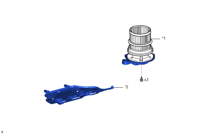
COMPONENTS
ILLUSTRATION
|
*1 |
BLOWER MOTOR WITH FAN SUB-ASSEMBLY |
*2 |
NO. 2 INSTRUMENT PANEL UNDER COVER SUB-ASSEMBLY |
Removal
REMOVAL
PROCEDURE
1. REMOVE NO. 2 INSTRUMENT PANEL UNDER COVER SUB-ASSEMBLY
Click here
.gif)
2. REMOVE BLOWER MOTOR WITH FAN SUB-ASSEMBLY
|
(a) Disengage the clamp. |
|
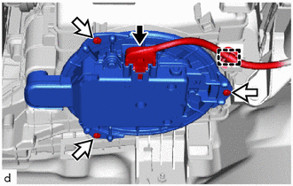
(b) Disconnect the connector.
(c) Remove the 3 screws and blower motor with fan sub-assembly.
NOTICE:
Replace the blower motor with fan sub-assembly if it has been dropped or subjected to a severe impact.
Installation
INSTALLATION
PROCEDURE
1. INSTALL BLOWER MOTOR WITH FAN SUB-ASSEMBLY
|
(a) Install the blower motor with fan sub-assembly with the 3 screws. NOTICE: Replace the blower motor with fan sub-assembly if it has been dropped or subjected to a severe impact. |
|
.png)
(b) Connect the connector.
(c) Engage the clamp.
2. INSTALL NO. 2 INSTRUMENT PANEL UNDER COVER SUB-ASSEMBLY
Click here
.gif)
 Installation
INSTALLATION
PROCEDURE
1. INSTALL COOLER CONDENSER ASSEMBLY
(a) Engage the 2 guides and 2 claws to install the cooler condenser assembly
as shown in the illustration.
Insta ...
 Front Blower Motor(for Valeo Made)
Components
COMPONENTS
ILLUSTRATION
*1
BLOWER MOTOR WITH FAN SUB-ASSEMBLY
*2
NO. 2 INSTRUMENT PANEL UNDER COVER SUB-ASSEMBLY
Removal
REMO ...
Other materials:
Toyota CH-R Service Manual > Toyota Entune System: Lost Communication with Body Control Module "B" (U0142,U0155,U0163)
DESCRIPTION
These DTCs are stored when a malfunction occurs in the CAN communication circuit.
HINT:
If CAN communication system DTCs are stored, they may also be stored for other
systems.
DTC No.
Detection Item
DTC Detection Condition
Trouble Area
...
Toyota CH-R Service Manual > Vehicle Stability Control System: System Description
SYSTEM DESCRIPTION
FUNCTION DESCRIPTION
(a) Enhanced-VSC
(1) Effects cooperative control with the power steering ECU assembly in order
to provide steering assist in accordance with the operating conditions of the vehicle.
(b) Anti-lock Brake System (ABS)
(1) The ABS helps prevent the wheels f ...
Toyota C-HR (AX20) 2023-2026 Owner's Manual
Toyota CH-R Owners Manual
- For safety and security
- Instrument cluster
- Operation of each component
- Driving
- Interior features
- Maintenance and care
- When trouble arises
- Vehicle specifications
- For owners
Toyota CH-R Service Manual
- Introduction
- Maintenance
- Audio / Video
- Cellular Communication
- Navigation / Multi Info Display
- Park Assist / Monitoring
- Brake (front)
- Brake (rear)
- Brake Control / Dynamic Control Systems
- Brake System (other)
- Parking Brake
- Axle And Differential
- Drive Shaft / Propeller Shaft
- K114 Cvt
- 3zr-fae Battery / Charging
- Networking
- Power Distribution
- Power Assist Systems
- Steering Column
- Steering Gear / Linkage
- Alignment / Handling Diagnosis
- Front Suspension
- Rear Suspension
- Tire / Wheel
- Tire Pressure Monitoring
- Door / Hatch
- Exterior Panels / Trim
- Horn
- Lighting (ext)
- Mirror (ext)
- Window / Glass
- Wiper / Washer
- Door Lock
- Heating / Air Conditioning
- Interior Panels / Trim
- Lighting (int)
- Meter / Gauge / Display
- Mirror (int)
- Power Outlets (int)
- Pre-collision
- Seat
- Seat Belt
- Supplemental Restraint Systems
- Theft Deterrent / Keyless Entry

0.0082