Toyota CH-R Service Manual: Installation
INSTALLATION
PROCEDURE
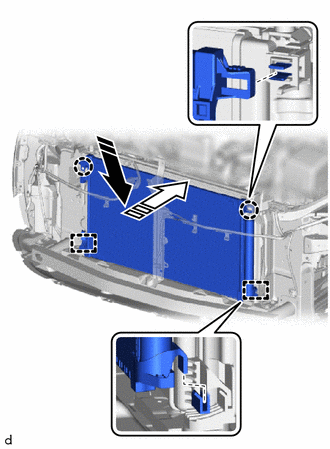
1. INSTALL COOLER CONDENSER ASSEMBLY
(a) Engage the 2 guides and 2 claws to install the cooler condenser assembly as shown in the illustration.
.png) |
Install in this Direction (1) |
.png) |
Install in this Direction (2) |
NOTICE:
Do not damage the cooler condenser assembly or radiator assembly when installing the cooler condenser assembly.
HINT:
If a new cooler condenser assembly is installed, add compressor oil to the cooler condenser assembly as follows.
Capacity:
Add 40 cc (1.35 fl. oz)
Compressor Oil:
for VALEO Made
VC100YF or equivalent
for DENSO Made
ND-OIL 12 or equivalent
2. CONNECT COOLER REFRIGERANT LIQUID PIPE A (for VALEO Made)
(a) Remove the vinyl tape from the cooler refrigerant liquid pipe A and cooler condenser assembly.
(b) Apply sufficient compressor oil to a new O-rings and fitting surfaces of the cooler refrigerant liquid pipe A
Compressor Oil:
VC100YF or equivalent
(c) Install the O-ring to the air cooler refrigerant liquid pipe A.
NOTICE:
Keep the O-rings and O-ring fitting surfaces free of foreign matter.
(d) Connect the cooler refrigerant liquid pipe A to the cooler condenser assembly with the bolt.
Torque:
5.4 N·m {55 kgf·cm, 48 in·lbf}
3. CONNECT COOLER REFRIGERANT LIQUID PIPE A (for DENSO Made)
(a) Remove the vinyl tape from the open ends of the cooler condenser assembly and cooler refrigerant liquid pipe A.
|
(b) Install a new piping clamp to the cooler refrigerant liquid pipe A. NOTICE:
|
|
(c) Thoroughly coat 2 new O-rings and the contact surface of the cooler refrigerant liquid pipe A with compressor oil.
Compressor Oil:
ND-OIL 12 or equivalent
(d) Install the 2 O-rings to the cooler refrigerant liquid pipe A.
NOTICE:
Do not let foreign matter adhere to the O-rings or O-ring seals.
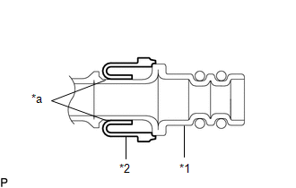
(e) Engage the cooler condenser assembly and cooler refrigerant liquid pipe A.
|
*a |
Large Diameter Section of Piping Clamp |
- |
- |
NOTICE:
Engage the parts by holding the pipe, not the piping clamp.
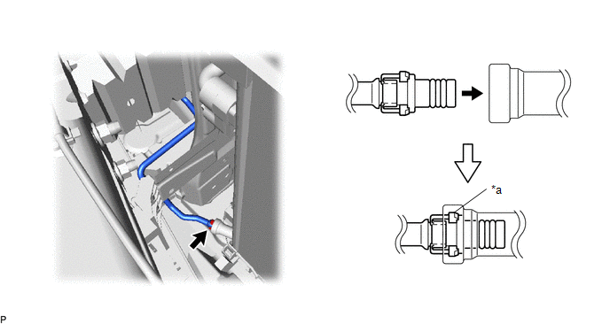
(f) Securely insert the piping clamp to the point where the large diameter section of the piping clamp is covered by the cooler condenser assembly.
HINT:
- When inserting, make sure that a click sound is heard.
- Check that the cooler refrigerant liquid pipe A is securely inserted by pulling it.
4. CONNECT DISCHARGE HOSE SUB-ASSEMBLY
(a) Remove the vinyl tape from the discharge hose sub-assembly and the connecting part of the cooler condenser assembly.
(b) Sufficiently apply compressor oil to a new O-ring and the fitting surface of the discharge hose sub-assembly.
Compressor Oil:
for VALEO Made
VC100YF or equivalent
for DENSO Made
ND-OIL 12 or equivalent
(c) Install the O-ring to the discharge hose sub-assembly.
(d) Connect the discharge hose sub-assembly to the cooler condenser assembly with the bolt.
Torque:
5.4 N·m {55 kgf·cm, 48 in·lbf}
5. INSTALL NO. 1 RADIATOR AIR GUIDE LH
Click here
.gif)
6. INSTALL NO. 1 RADIATOR AIR GUIDE RH
Click here
7. INSTALL FRONT BUMPER REINFORCEMENT
Click here
8. INSTALL FRONT BUMPER ENERGY ABSORBER
Click here
9. INSTALL NO. 2 RADIATOR AIR GUIDE
Click here
10. INSTALL UPPER RADIATOR SUPPORT SUB-ASSEMBLY
Click here
11. INSTALL HOOD LOCK ASSEMBLY
- w/ Engine Hood Courtesy Switch:
Click here
- w/o Engine Hood Courtesy Switch:
Click here
12. INSTALL HOOD LOCK NUT CAP
Click here
13. INSTALL NO. 1 RADIATOR TO SUPPORT SEAL
Click here
14. INSTALL NO. 1 RADIATOR GRILLE RETAINER
Click here
15. INSTALL FRONT BUMPER UPPER REINFORCEMENT SUB-ASSEMBLY
Click here
16. INSTALL NO. 1 AIR CLEANER INLET
Click here
17. INSTALL HEADLIGHT ASSEMBLY LH (for Halogen Headlight)
Click here
18. INSTALL HEADLIGHT ASSEMBLY LH (for LED Headlight)
Click here
19. INSTALL HEADLIGHT ASSEMBLY RH (for Halogen Headlight)
HINT:
Use the same procedure as for the LH side.
20. INSTALL HEADLIGHT ASSEMBLY RH (for LED Headlight)
HINT:
Use the same procedure as for the LH side.
21. CHARGE AIR CONDITIONING SYSTEM WITH REFRIGERANT (for HFC-134a(R134a))
Click here
22. CHARGE AIR CONDITIONING SYSTEM WITH REFRIGERANT (for HFO-1234yf(R1234yf))
Click here
23. WARM UP ENGINE (for HFC-134a(R134a))
Click here
24. WARM UP ENGINE (for HFO-1234yf(R1234yf))
Click here
25. INSPECT FOR REFRIGERANT LEAK (for HFC-134a(R134a))
Click here
26. INSPECT FOR REFRIGERANT LEAK (for HFO-1234yf(R1234yf))
Click here
27. ADJUST HOOD LOCK ASSEMBLY
Click here
 Reassembly
REASSEMBLY
PROCEDURE
1. INSTALL COOLER DRYER (for VALEO Made)
(a) Using needle-nose pliers install a new cooler dryer to the modulator.
...
 Front Blower Motor(for Denso Made)
Components
COMPONENTS
ILLUSTRATION
*1
BLOWER MOTOR WITH FAN SUB-ASSEMBLY
*2
NO. 2 INSTRUMENT PANEL UNDER COVER SUB-ASSEMBLY
Removal
REMO ...
Other materials:
Toyota CH-R Owners Manual > Tire information: Typical tire symbols
Full-size tire
Compact spare tire
Tire size
DOT and Tire Identification Number (TIN)
Uniform tire quality grading
For details, see "Uniform Tire Quality Grading" that follows.
Location of treadwear indicators
Tire ply composition and materials
Plies are layers o ...
Toyota CH-R Service Manual > Seat Belt Warning System(w/o Occupant Classification System): Problem Symptoms Table
PROBLEM SYMPTOMS TABLE
HINT:
Use the table below to help determine the cause of problem symptoms.
If multiple suspected areas are listed, the potential causes of the symptoms
are listed in order of probability in the "Suspected Area" column of the
table. Check each sy ...
Toyota C-HR (AX20) 2023-2026 Owner's Manual
Toyota CH-R Owners Manual
- For safety and security
- Instrument cluster
- Operation of each component
- Driving
- Interior features
- Maintenance and care
- When trouble arises
- Vehicle specifications
- For owners
Toyota CH-R Service Manual
- Introduction
- Maintenance
- Audio / Video
- Cellular Communication
- Navigation / Multi Info Display
- Park Assist / Monitoring
- Brake (front)
- Brake (rear)
- Brake Control / Dynamic Control Systems
- Brake System (other)
- Parking Brake
- Axle And Differential
- Drive Shaft / Propeller Shaft
- K114 Cvt
- 3zr-fae Battery / Charging
- Networking
- Power Distribution
- Power Assist Systems
- Steering Column
- Steering Gear / Linkage
- Alignment / Handling Diagnosis
- Front Suspension
- Rear Suspension
- Tire / Wheel
- Tire Pressure Monitoring
- Door / Hatch
- Exterior Panels / Trim
- Horn
- Lighting (ext)
- Mirror (ext)
- Window / Glass
- Wiper / Washer
- Door Lock
- Heating / Air Conditioning
- Interior Panels / Trim
- Lighting (int)
- Meter / Gauge / Display
- Mirror (int)
- Power Outlets (int)
- Pre-collision
- Seat
- Seat Belt
- Supplemental Restraint Systems
- Theft Deterrent / Keyless Entry

0.007