Toyota CH-R Service Manual: Front Blower Motor(for Valeo Made)
Components
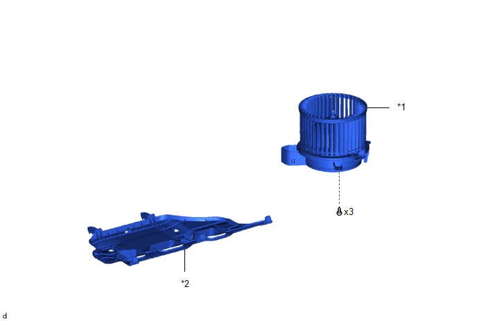
COMPONENTS
ILLUSTRATION
|
*1 |
BLOWER MOTOR WITH FAN SUB-ASSEMBLY |
*2 |
NO. 2 INSTRUMENT PANEL UNDER COVER SUB-ASSEMBLY |
Removal
REMOVAL
PROCEDURE
1. REMOVE NO. 2 INSTRUMENT PANEL UNDER COVER SUB-ASSEMBLY
Click here
.gif)
2. REMOVE BLOWER MOTOR WITH FAN SUB-ASSEMBLY
|
(a) Disconnect the connector. |
|
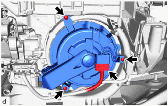
(b) Remove the 3 screws and blower motor with fan sub-assembly.
NOTICE:
Replace the blower motor with fan sub-assembly if it has been dropped or subjected to a severe impact.
Inspection
INSPECTION
PROCEDURE
1. INSPECT BLOWER WITH FAN MOTOR SUB-ASSEMBLY
|
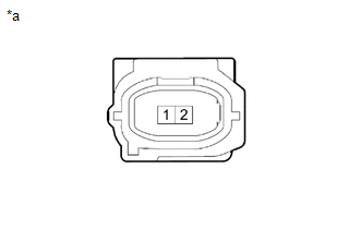
(a) Check the operation. (1) Apply battery voltage to the blower with fan motor sub-assembly and check the operation of the motor. Specified Condition:
If the result is not as specified, replace the blower with fan motor sub-assembly. |
|
Installation
INSTALLATION
PROCEDURE
1. INSTALL BLOWER MOTOR WITH FAN SUB-ASSEMBLY
(a) Install the blower motor with fan sub-assembly with the 3 screws.
NOTICE:
Replace the blower motor with fan sub-assembly if it has been dropped or subjected to a severe impact.
(b) Connect the connector.
2. INSTALL NO. 2 INSTRUMENT PANEL UNDER COVER SUB-ASSEMBLY
Click here
.gif)
 Front Blower Motor(for Denso Made)
Components
COMPONENTS
ILLUSTRATION
*1
BLOWER MOTOR WITH FAN SUB-ASSEMBLY
*2
NO. 2 INSTRUMENT PANEL UNDER COVER SUB-ASSEMBLY
Removal
REMO ...

Other materials:
Toyota CH-R Service Manual > Airbag System: Parts Location
PARTS LOCATION
ILLUSTRATION
*1
FRONT AIRBAG SENSOR LH
*2
FRONT AIRBAG SENSOR RH
*3
DOOR SIDE AIRBAG SENSOR LH
*4
DOOR SIDE AIRBAG SENSOR RH
*5
NO. 1 SIDE AIRBAG SENSOR LH
...
Toyota CH-R Service Manual > Power Door Lock Control System: Data List / Active Test
DATA LIST / ACTIVE TEST
DATA LIST
HINT:
Using the Techstream to read the Data List allows the values or states of switches,
sensors, actuators and other items to be read without removing any parts. This non-intrusive
inspection can be very useful because intermittent conditions or signals may ...
Toyota C-HR (AX20) 2023-2026 Owner's Manual
Toyota CH-R Owners Manual
- For safety and security
- Instrument cluster
- Operation of each component
- Driving
- Interior features
- Maintenance and care
- When trouble arises
- Vehicle specifications
- For owners
Toyota CH-R Service Manual
- Introduction
- Maintenance
- Audio / Video
- Cellular Communication
- Navigation / Multi Info Display
- Park Assist / Monitoring
- Brake (front)
- Brake (rear)
- Brake Control / Dynamic Control Systems
- Brake System (other)
- Parking Brake
- Axle And Differential
- Drive Shaft / Propeller Shaft
- K114 Cvt
- 3zr-fae Battery / Charging
- Networking
- Power Distribution
- Power Assist Systems
- Steering Column
- Steering Gear / Linkage
- Alignment / Handling Diagnosis
- Front Suspension
- Rear Suspension
- Tire / Wheel
- Tire Pressure Monitoring
- Door / Hatch
- Exterior Panels / Trim
- Horn
- Lighting (ext)
- Mirror (ext)
- Window / Glass
- Wiper / Washer
- Door Lock
- Heating / Air Conditioning
- Interior Panels / Trim
- Lighting (int)
- Meter / Gauge / Display
- Mirror (int)
- Power Outlets (int)
- Pre-collision
- Seat
- Seat Belt
- Supplemental Restraint Systems
- Theft Deterrent / Keyless Entry

0.0445