Toyota CH-R Service Manual: Removal
REMOVAL
PROCEDURE
1. RECOVER REFRIGERANT FROM REFRIGERATION SYSTEM (for HFO-1234yf(R1234yf))
Click here
.gif)
2. REMOVE NO. 1 ENGINE UNDER COVER
Click here
3. REMOVE FAN AND GENERATOR V BELT
Click here
4. DISCONNECT DISCHARGE HOSE SUB-ASSEMBLY
|
(a) Disconnect the connector. |
|
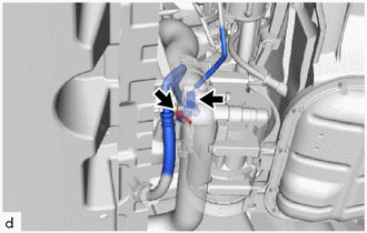
(b) Remove the bolt to disconnect the discharge hose sub-assembly from the compressor with pulley assembly.
(c) Remove the O-ring from the discharge hose sub-assembly.
NOTICE:
Seal the openings of the disconnected parts using vinyl tape to prevent moisture and foreign matter from entering them.
5. DISCONNECT SUCTION HOSE SUB-ASSEMBLY
|
(a) Remove the bolt to disconnect the suction hose sub-assembly from the compressor with pulley assembly. |
|
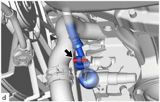
(b) Remove the O-ring from the suction hose sub-assembly.
NOTICE:
Seal the openings of the disconnected parts using vinyl tape to prevent moisture and foreign matter from entering them.
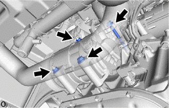
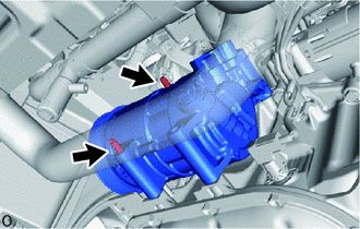
6. REMOVE COMPRESSOR WITH PULLEY ASSEMBLY
|
(a) Remove the 2 bolts and 2 nuts. |
|
|
(b) Using an E8 "TORX" socket wrench, remove the 2 stud bolts and compressor with pulley assembly. HINT: Remove the compressor with pulley assembly from the vehicle with the stud bolts remaining in the compressor with pulley assembly. |
|
 Inspection
INSPECTION
PROCEDURE
1. INSPECT COMPRESSOR WITH PULLEY ASSEMBLY
(a) Measure the resistance according to the value(s) in the table below.
Standard Resistance:
Test ...
 Installation
INSTALLATION
PROCEDURE
1. ADJUST COMPRESSOR OIL
(a) When replacing the compressor with pulley assembly with a new one,
gradually discharge the refrigerant gas from the service valve. ...
Other materials:
Toyota CH-R Service Manual > Front Lower Ball Joint: Components
COMPONENTS
ILLUSTRATION
*1
FRONT AXLE ASSEMBLY
*2
FRONT LOWER BALL JOINT ASSEMBLY
*3
COTTER PIN
-
-
Tightening torque for "Major areas involving basic vehicle performance ...
Toyota CH-R Service Manual > Vehicle Stability Control System: Check For Intermittent Problems
CHECK FOR INTERMITTENT PROBLEMS
CHECK FOR INTERMITTENT PROBLEMS
HINT:
A momentary interruption (open circuit) in the connectors and/or wire harness
between the sensors and ECUs can be detected using the Data List function of the
Techstream.
(a) Turn the ignition switch off.
(b) Connect the ...
Toyota C-HR (AX20) 2023-2026 Owner's Manual
Toyota CH-R Owners Manual
- For safety and security
- Instrument cluster
- Operation of each component
- Driving
- Interior features
- Maintenance and care
- When trouble arises
- Vehicle specifications
- For owners
Toyota CH-R Service Manual
- Introduction
- Maintenance
- Audio / Video
- Cellular Communication
- Navigation / Multi Info Display
- Park Assist / Monitoring
- Brake (front)
- Brake (rear)
- Brake Control / Dynamic Control Systems
- Brake System (other)
- Parking Brake
- Axle And Differential
- Drive Shaft / Propeller Shaft
- K114 Cvt
- 3zr-fae Battery / Charging
- Networking
- Power Distribution
- Power Assist Systems
- Steering Column
- Steering Gear / Linkage
- Alignment / Handling Diagnosis
- Front Suspension
- Rear Suspension
- Tire / Wheel
- Tire Pressure Monitoring
- Door / Hatch
- Exterior Panels / Trim
- Horn
- Lighting (ext)
- Mirror (ext)
- Window / Glass
- Wiper / Washer
- Door Lock
- Heating / Air Conditioning
- Interior Panels / Trim
- Lighting (int)
- Meter / Gauge / Display
- Mirror (int)
- Power Outlets (int)
- Pre-collision
- Seat
- Seat Belt
- Supplemental Restraint Systems
- Theft Deterrent / Keyless Entry

0.0089