Toyota CH-R Service Manual: Reassembly
REASSEMBLY
PROCEDURE
1. INSTALL NO. 1 BLOWER DAMPER SERVO SUB-ASSEMBLY
|
(a) Connect the 2 links of the blower assembly to the 2 plates of the No. 1 blower damper servo sub-assembly as shown in the illustration. |
|
(b) Install the No. 1 blower damper servo sub-assembly with the 2 screws.
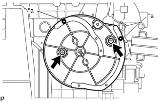
2. INSTALL BLOWER MOTOR WITH FAN SUB-ASSEMBLY
|
(a) Install the blower motor with fan sub-assembly with the 3 screws. NOTICE: Replace the blower motor with fan sub-assembly if it has been dropped or subjected to a severe impact. |
|
.png)
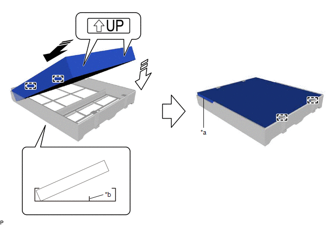
3. INSTALL CLEAN AIR FILTER
(a) Engage the guides on the cutout side of the cooling unit parts and then engage the guides as shown in the illustration to install the clean air filter.
|
*a |
Cutout |
*b |
Rib |
.png) |
Install in this Direction (1) |
.png) |
Install in this Direction (2) |
NOTICE:
- Make sure that the "UP" marks are facing the correct direction before installing the clean air filter.
- Make sure that there is no clearance between the clean air filter and cooling unit parts and that the clean air filter is not deformed.
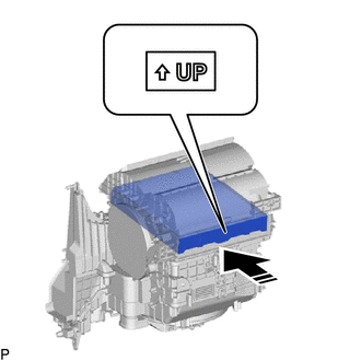
(b) Install the air filter sub-assembly as shown in the illustration.
|
|
Install in this Direction |
NOTICE:
Make sure that the "UP" mark is facing the correct direction before installing the air filter sub-assembly.
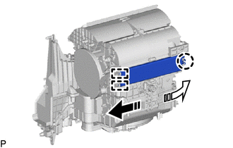
4. INSTALL AIR FILTER COVER PLATE
(a) Engage the guides and claw as shown in the illustration to install the air filter cover plate.
|
|
Install in this Direction (1) |
|
|
Install in this Direction (2) |
 Removal
REMOVAL
CAUTION / NOTICE / HINT
The necessary procedures (adjustment, calibration, initialization or registration)
that must be performed after parts are removed and installed, or replaced during ...
 Installation
INSTALLATION
PROCEDURE
1. INSTALL BLOWER ASSEMBLY
(a) Engage the guides to install the air conditioning radiator assembly.
(b) Install th ...
Other materials:
Toyota CH-R Service Manual > Front Drive Shaft Assembly: Components
COMPONENTS
ILLUSTRATION
*1
NO. 1 ENGINE UNDER COVER
*2
REAR ENGINE UNDER COVER LH
*3
REAR ENGINE UNDER COVER RH
-
-
N*m (kgf*cm, ft.*lbf): Specified torque
-
...
Toyota CH-R Service Manual > Brake Fluid: Components
COMPONENTS
ILLUSTRATION
*A
for TMC Made
-
-
*1
CENTER NO. 1 COWL TOP VENTILATOR LOUVER
*2
BRAKE MASTER CYLINDER RESERVOIR CAP ASSEMBLY
*3
FRONT DISC BRAKE BLEEDER PLUG
...
Toyota C-HR (AX20) 2023-2026 Owner's Manual
Toyota CH-R Owners Manual
- For safety and security
- Instrument cluster
- Operation of each component
- Driving
- Interior features
- Maintenance and care
- When trouble arises
- Vehicle specifications
- For owners
Toyota CH-R Service Manual
- Introduction
- Maintenance
- Audio / Video
- Cellular Communication
- Navigation / Multi Info Display
- Park Assist / Monitoring
- Brake (front)
- Brake (rear)
- Brake Control / Dynamic Control Systems
- Brake System (other)
- Parking Brake
- Axle And Differential
- Drive Shaft / Propeller Shaft
- K114 Cvt
- 3zr-fae Battery / Charging
- Networking
- Power Distribution
- Power Assist Systems
- Steering Column
- Steering Gear / Linkage
- Alignment / Handling Diagnosis
- Front Suspension
- Rear Suspension
- Tire / Wheel
- Tire Pressure Monitoring
- Door / Hatch
- Exterior Panels / Trim
- Horn
- Lighting (ext)
- Mirror (ext)
- Window / Glass
- Wiper / Washer
- Door Lock
- Heating / Air Conditioning
- Interior Panels / Trim
- Lighting (int)
- Meter / Gauge / Display
- Mirror (int)
- Power Outlets (int)
- Pre-collision
- Seat
- Seat Belt
- Supplemental Restraint Systems
- Theft Deterrent / Keyless Entry

0.0081