Toyota CH-R Service Manual: Terminals Of Ecu
TERMINALS OF ECU
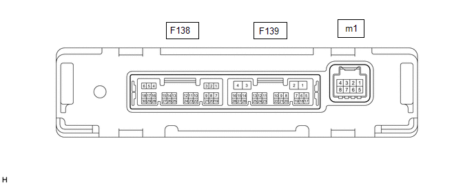
AIR CONDITIONING AMPLIFIER ASSEMBLY
HINT:
Check from the rear of the connector while it is connected to the air conditioning amplifier assembly.
|
Terminal No. (Symbol) |
Wiring Color |
Terminal Description |
Condition |
Specified Condition |
|---|---|---|---|---|
|
F138-1 (SG-1) - Body ground |
LG - Body ground |
Ground for cooler thermistor (room temperature sensor) |
Always |
Below 1 V |
|
F138-2 (SG-2) - Body ground |
G - Body ground |
Ground for air conditioner pressure sensor |
Always |
Below 1 V |
|
F138-6 (S5-3) - F138-2 (SG-2) |
GR - G |
Power supply for air conditioner pressure sensor |
Ignition switch ON |
4.75 to 5.25 V |
|
Ignition switch off |
Below 1 V |
|||
|
F138-14 (TR) - F138-1 (SG-1) |
B - LG |
Cooler thermistor (room temperature sensor) signal |
|
1.8 to 2.2 V |
|
1.2 to 1.6 V |
|||
|
F138-24 (PRE) - F138-2 (SG-2) |
V - G |
Air conditioner pressure sensor signal |
|
4.61 V or higher |
|
Below 0.74 V |
|||
|
0.74 to 4.61 V |
|||
|
F139-1 (B) - F139-4 (GND) |
V - W-B |
Power source (Back-up) |
Always |
11 to 14 V |
|
F139-2 (IG+) - F139-4 (GND) |
B - W-B |
Power source (IG) |
Ignition switch ON |
11 to 14 V |
|
Ignition switch off |
Below 1 V |
|||
|
F139-3 (SOL+) - F139-4 (GND) |
B - W-B |
Compressor solenoid operation signal |
|
Pulse generation (See waveform 1) |
|
F139-4 (GND) - Body ground |
W-B - Body ground |
Ground for main power supply |
Always |
Below 1 V |
|
F139-6 (BLW) - F139-4 (GND) |
Y - W-B |
Blower motor speed control signal |
|
Pulse generation (See waveform 2) |
|
F139-11 (CANH) - F139-12 (CANL) |
P - SB |
CAN communication signal |
CAN communication is performed |
Pulse generation |
|
F139-14 (LIN1) - F139-4 (GND) |
BE - W-B |
LIN communication signal (Air conditioning control assembly) |
Ignition switch ON |
Pulse generation (See waveform 3) |
|
m1-2 (BUSG) - Body ground |
B - Body ground |
Ground for BUS IC |
Always |
Below 1 V |
|
m1-3 (BUS) - m1-2 (BUSG) |
L - B |
BUS IC control signal |
Ignition switch ON |
Pulse generation (See waveform 4) |
|
m1-4 (BUSB) - m1-2 (BUSG) |
R - B |
Power supply for BUS IC |
Always |
11 to 14 V |
|
m1-5 (SG-4) - Body ground |
GR - Body ground |
Ground for No. 1 cooler thermistor (evaporator temperature sensor) |
Always |
Below 1 V |
|
m1-6 (TE) - m1-5 (SG-4) |
GR - GR |
No. 1 cooler thermistor (evaporator temperature sensor) |
|
1.7 to 2.1 V |
|
0.9 to 1.3 V |
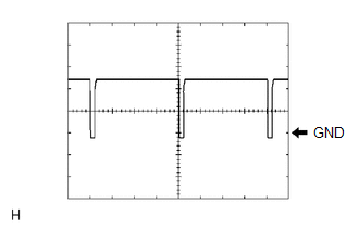
(a) Waveform 1:
|
Item |
Content |
|---|---|
|
Terminal No. (Symbol) |
F139-3 (SOL+) - F139-4 (GND) |
|
Tool Setting |
5 V/DIV., 500 μs/DIV. |
|
Vehicle Condition |
|
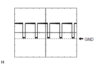
(b) Waveform 2:
|
Item |
Content |
|---|---|
|
Terminal No. |
F139-6 (BLW) - F139-4 (GND) |
|
Tool Setting |
2 V/DIV., 1 ms./DIV. |
|
Vehicle Condition |
|
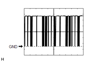
(c) Waveform 3:
|
Item |
Content |
|---|---|
|
Terminal No. |
F139-14 (LIN1) - F139-4 (GND) |
|
Tool Setting |
2 V/DIV., 20 ms./DIV. |
|
Vehicle Condition |
Ignition switch ON |
(d) Waveform 4:
|
Item |
Content |
|---|---|
|
Terminal No. |
m1-3 (BUS) - m1-2 (BUS G) |
|
Tool Setting |
2 V/DIV., 2 ms./DIV. |
|
Vehicle Condition |
Ignition switch ON |
AIR CONDITIONING CONTROL ASSEMBLY
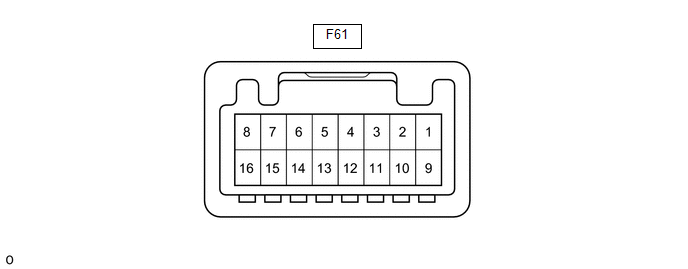
HINT:
Check from the rear of the connector while it is connected to the air conditioning control assembly.
|
Terminal No. (Symbol) |
Wiring Color |
Terminal Description |
Condition |
Specified Condition |
|---|---|---|---|---|
|
F61-16 (GND) - Body ground |
W-B - Body ground |
Ground for air conditioning control assembly |
Always |
Below 1 V |
|
F61-2 (LIN1) - Body ground |
BE - Body ground |
LIN communication signal |
Ignition switch ON |
Pulse generation (See waveform 1) |
|
F61-10 (IG+) - F61-16 (GND) |
BE - W-B |
Power source (IG) |
Ignition switch off |
Below 1 V |
|
Ignition switch ON |
11 to 14 V |
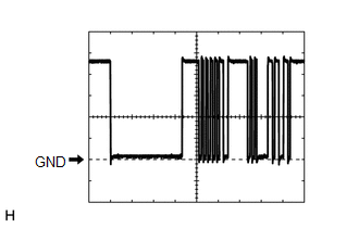
(a) Waveform 1:
|
Item |
Content |
|---|---|
|
Terminal No. |
F61-2 (LIN1) - Body ground |
|
Tool Setting |
2 V/DIV., 20 ms./DIV. |
|
Vehicle Condition |
Ignition switch ON |
 Problem Symptoms Table
PROBLEM SYMPTOMS TABLE
HINT:
Use the table below to help determine the cause of problem symptoms.
If multiple suspected areas are listed, the potential causes of the symptoms
are lis ...
 Diagnosis System
DIAGNOSIS SYSTEM
DESCRIPTION
Air conditioning system data and Diagnostic Trouble Codes (DTCs) can be read
through the Data Link Connector 3 (DLC3) of the vehicle. When the system seems to
be mal ...
Other materials:
Toyota CH-R Service Manual > Knee Airbag Assembly: On-vehicle Inspection
ON-VEHICLE INSPECTION
CAUTION / NOTICE / HINT
CAUTION:
Be sure to correctly follow the removal and installation procedures for the lower
No. 1 instrument panel airbag assembly.
PROCEDURE
1. INSPECT LOWER NO. 1 INSTRUMENT PANEL AIRBAG ASSEMBLY (for Vehicle not Involved
in Collision)
(a) Per ...
Toyota CH-R Service Manual > Meter / Gauge System: System Description
SYSTEM DESCRIPTION
INPUT AND OUTPUT SIGNALS OF COMBINATION METER ASSEMBLY
(a) Meter or Gauge
Item
Condition
Input/Output
Communication line
Signal
Component
Speedometer
Gauge
Input
...
Toyota C-HR (AX20) 2023-2026 Owner's Manual
Toyota CH-R Owners Manual
- For safety and security
- Instrument cluster
- Operation of each component
- Driving
- Interior features
- Maintenance and care
- When trouble arises
- Vehicle specifications
- For owners
Toyota CH-R Service Manual
- Introduction
- Maintenance
- Audio / Video
- Cellular Communication
- Navigation / Multi Info Display
- Park Assist / Monitoring
- Brake (front)
- Brake (rear)
- Brake Control / Dynamic Control Systems
- Brake System (other)
- Parking Brake
- Axle And Differential
- Drive Shaft / Propeller Shaft
- K114 Cvt
- 3zr-fae Battery / Charging
- Networking
- Power Distribution
- Power Assist Systems
- Steering Column
- Steering Gear / Linkage
- Alignment / Handling Diagnosis
- Front Suspension
- Rear Suspension
- Tire / Wheel
- Tire Pressure Monitoring
- Door / Hatch
- Exterior Panels / Trim
- Horn
- Lighting (ext)
- Mirror (ext)
- Window / Glass
- Wiper / Washer
- Door Lock
- Heating / Air Conditioning
- Interior Panels / Trim
- Lighting (int)
- Meter / Gauge / Display
- Mirror (int)
- Power Outlets (int)
- Pre-collision
- Seat
- Seat Belt
- Supplemental Restraint Systems
- Theft Deterrent / Keyless Entry

0.0087