Toyota CH-R Service Manual: Parts Location
PARTS LOCATION
ILLUSTRATION
|
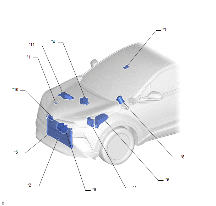
*1 |
AIR CONDITIONER PRESSURE SENSOR |
*2 |
THERMISTOR ASSEMBLY |
|
*3 |
FORWARD RECOGNITION CAMERA |
*4 |
BRAKE ACTUATOR ASSEMBLY (SKID CONTROL ECU) |
|
*5 |
COOLER CONDENSER ASSEMBLY |
*6 |
NO. 1 ENGINE ROOM RELAY BLOCK - HTR FUSE |
|
*7 |
ECM |
*8 |
POWER STEERING ECU ASSEMBLY |
|
*9 |
COMPRESSOR WITH PULLEY ASSEMBLY |
*10 |
MILLIMETER WAVE RADAR SENSOR ASSEMBLY |
|
*11 |
NO. 2 ENGINE ROOM RELAY BLOCK - PTC HTR NO. 1 RELAY - PTC HTR NO. 2 RELAY - PTC HTR NO. 3 RELAY |
- |
- |
ILLUSTRATION
|
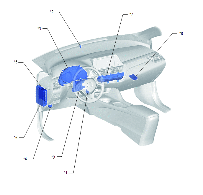
*1 |
COOLER THERMISTOR (ROOM TEMPERATURE SENSOR) |
*2 |
AUTOMATIC LIGHT CONTROL SENSOR |
|
*3 |
COMBINATION METER ASSEMBLY |
*4 |
DLC3 |
|
*5 |
MAIN BODY ECU (MULTIPLEX NETWORK BODY ECU) |
*6 |
INSTRUMENT PANEL JUNCTION BLOCK ASSEMBLY - ECU-B NO. 2 FUSE - ECU-IG1 NO. 3 FUSE - ECU-IG1 NO. 4 FUSE |
|
*7 |
AIR CONDITIONING CONTROL ASSEMBLY |
*8 |
NETWORK GATEWAY ECU |
|
*9 |
AIR CONDITIONING AMPLIFIER ASSEMBLY |
- |
- |
ILLUSTRATION
|
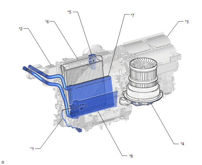
*1 |
NO. 1 COOLER THERMISTOR (EVAPORATOR TEMPERATURE SENSOR) |
*2 |
AIR CONDITIONING RADIATOR ASSEMBLY |
|
*3 |
BLOWER ASSEMBLY |
*4 |
BLOWER MOTOR WITH FAN SUB-ASSEMBLY |
|
*5 |
COOLER EXPANSION VALVE |
*6 |
NO. 1 COOLER EVAPORATOR SUB-ASSEMBLY |
|
*7 |
HEATER RADIATOR UNIT SUB-ASSEMBLY |
*8 |
QUICK HEATER ASSEMBLY |
ILLUSTRATION
|
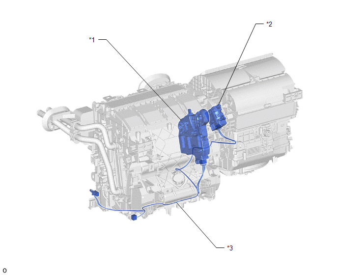
*1 |
NO. 1 AIR CONDITIONING RADIATOR DAMPER SERVO SUB-ASSEMBLY |
*2 |
NO. 1 BLOWER DAMPER SERVO SUB-ASSEMBLY |
|
*3 |
AIR CONDITIONING HARNESS ASSEMBLY |
- |
- |
 Precaution
PRECAUTION
IGNITION SWITCH EXPRESSIONS
(a) The type of ignition switch used on this model differs according to the specifications
of the vehicle. The expressions listed in the table below are used ...
 System Diagram
SYSTEM DIAGRAM
Communication Table
Sender
Receiver
Signal
Communication Line
Air conditioning amplifier assembly
ECM
...
Other materials:
Toyota CH-R Service Manual > Seat Belt Warning System(w/o Occupant Classification System): System Description
SYSTEM DESCRIPTION
SEAT BELT WARNING SYSTEM DESCRIPTION
(a) Seat belt warning light operation for driver seat belt:
The seat belt warning light on the combination meter assembly blinks or turns
off in accordance with the driver seat belt state and vehicle speed.
(b) Seat belt warning light ope ...
Toyota CH-R Service Manual > Continuously Variable Transaxle System: Acceleration Sensor Learning Value (P1589)
DESCRIPTION
The ECM stores DTC P1589 if deceleration sensor zero point calibration is not
performed or failed after system components such as the ECM are replaced.
DTC No.
Detection Item
DTC Detection Condition
Trouble Area
MIL
Me ...
Toyota C-HR (AX20) 2023-2026 Owner's Manual
Toyota CH-R Owners Manual
- For safety and security
- Instrument cluster
- Operation of each component
- Driving
- Interior features
- Maintenance and care
- When trouble arises
- Vehicle specifications
- For owners
Toyota CH-R Service Manual
- Introduction
- Maintenance
- Audio / Video
- Cellular Communication
- Navigation / Multi Info Display
- Park Assist / Monitoring
- Brake (front)
- Brake (rear)
- Brake Control / Dynamic Control Systems
- Brake System (other)
- Parking Brake
- Axle And Differential
- Drive Shaft / Propeller Shaft
- K114 Cvt
- 3zr-fae Battery / Charging
- Networking
- Power Distribution
- Power Assist Systems
- Steering Column
- Steering Gear / Linkage
- Alignment / Handling Diagnosis
- Front Suspension
- Rear Suspension
- Tire / Wheel
- Tire Pressure Monitoring
- Door / Hatch
- Exterior Panels / Trim
- Horn
- Lighting (ext)
- Mirror (ext)
- Window / Glass
- Wiper / Washer
- Door Lock
- Heating / Air Conditioning
- Interior Panels / Trim
- Lighting (int)
- Meter / Gauge / Display
- Mirror (int)
- Power Outlets (int)
- Pre-collision
- Seat
- Seat Belt
- Supplemental Restraint Systems
- Theft Deterrent / Keyless Entry

0.0079