Toyota CH-R Service Manual: System Diagram
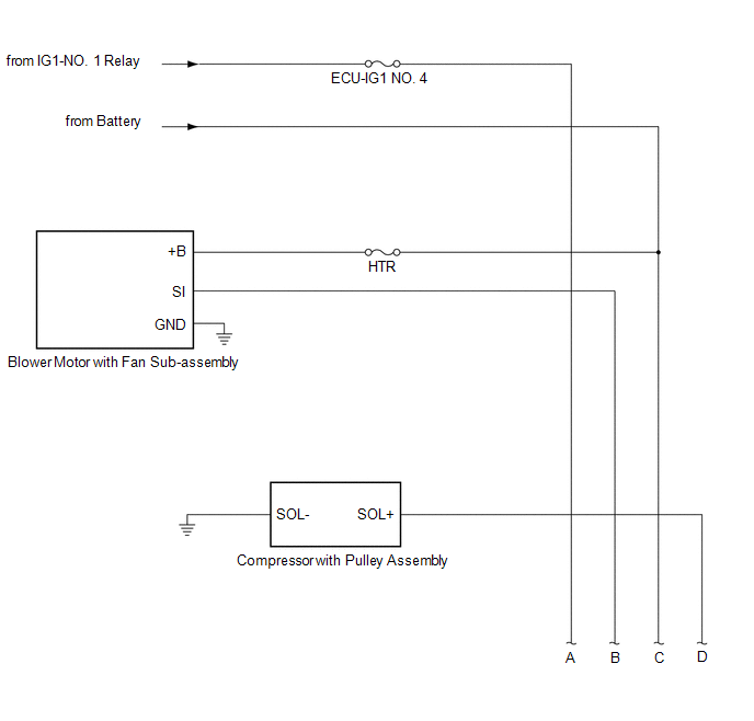
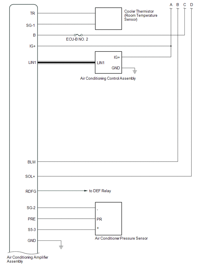
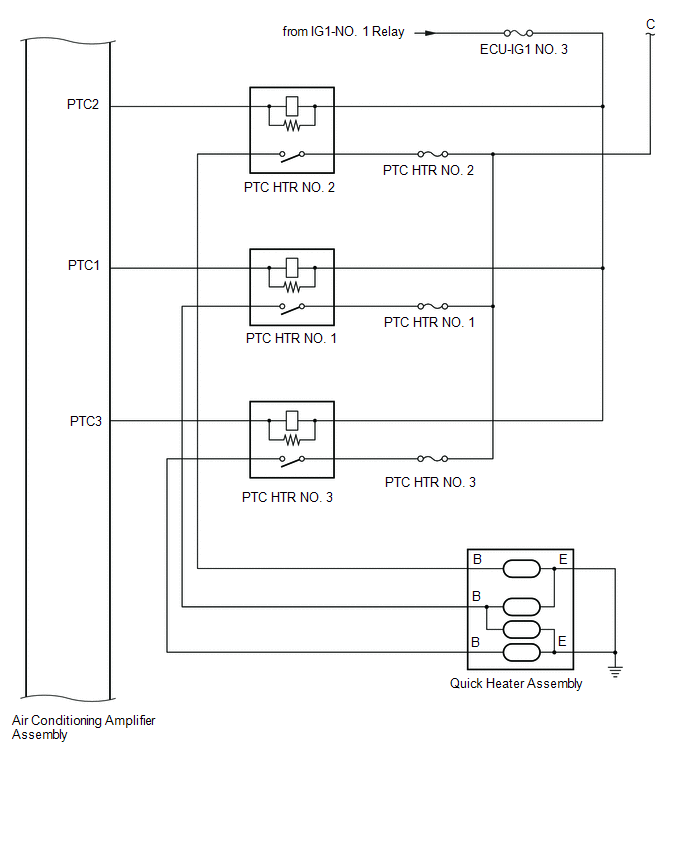
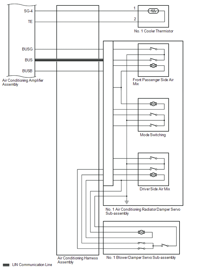
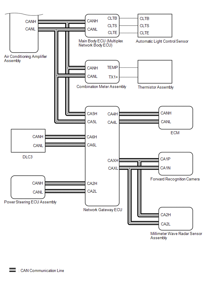
SYSTEM DIAGRAM
 Communication Table
|
Sender |
Receiver |
Signal |
Communication Line |
|---|---|---|---|
|
Air conditioning amplifier assembly |
ECM |
Magnet Clutch request signal |
CAN |
|
A/C Idleup request signal |
|||
|
Heater Idleup request signal |
|||
|
ECO SW information |
|||
|
Blower on state signal |
|||
|
Supercooling control state signal |
|||
|
Charging control inhibit signal |
|||
|
Prior A/C control request signal |
|||
|
Acceleration Cut inhibit signal |
|||
|
LOCK-UP INHIBIT signal |
|||
|
Generator control inhibit signal |
|||
|
Ambient temperature before correction, signal |
|||
|
Refrigerant information |
|||
|
The first advancement evaporator temperature |
|||
|
Variable compressor solenoid current signal |
|||
|
refrigerant gas pressure sensor signal |
|||
|
Rr DEF drive request signal |
|||
|
Ambient temperature display signal |
|||
|
Air conditioning amplifier assembly |
Combination meter assembly |
Ambient temperature display signal |
CAN |
|
A/C control state signal |
|||
|
Air conditioning amplifier assembly |
Brake actuator assembly (Skid control ECU) |
In-Vehicle temperature signal |
CAN |
|
Ambient temperature display signal |
|||
|
Air conditioning amplifier assembly |
Forward recognition camera |
Ambient temperature display signal |
CAN |
|
Air conditioning amplifier assembly |
Millimeter wave radar sensor assembly |
Ambient temperature display signal |
CAN |
|
ECM |
Air conditioning amplifier assembly |
Drive Mode Select Signal |
CAN |
|
Engine type information 1 |
|||
|
Engine type information 2 |
|||
|
Engine type information 3 |
|||
|
Engine type information 4 |
|||
|
HV flag |
|||
|
Eco-Run flag |
|||
|
Engine RPM data |
|||
|
Water temperature signal |
|||
|
Alternative field duty value |
|||
|
A/C control cut-off signal 4 |
|||
|
A/C control cut-off signal 2 |
|||
|
A/C control cut-off signal 2 |
|||
|
A/C control cut-off signal 1 |
|||
|
Variable control inhibition signal |
|||
|
Air conditioner cut-off instruction flag at deceleration |
|||
|
A/C supercooling command flag at deceleration |
|||
|
A/C lubrication control inhibit |
|||
|
Compulsory internal air circulation command signal at high water temperature |
|||
|
Main body ECU (multiplex network body ECU) |
Air conditioning amplifier assembly |
Auto dimmer signal |
CAN |
|
High beam head lamp request |
|||
|
Low beam head lamp request |
|||
|
Tail lamp request |
|||
|
Destination Symbol |
|||
|
Destination Package1 |
|||
|
Destination Package2 |
|||
|
Steering Wheel |
|||
|
Solar data(R) |
|||
|
Solar data(L) |
|||
|
Combination meter assembly |
Air conditioning amplifier assembly |
Outside temperature sensor data |
CAN |
|
Vehicle speed signal (meter to other) |
|||
|
Power steering ECU assembly |
Air conditioning amplifier assembly |
Loading control level |
CAN |
|
Air conditioning amplifier assembly |
Air conditioning control assembly |
A/C ECO indication request signal |
LIN |
|
Entire panel indication request signal |
|||
|
AUTO indication request signal |
|||
|
Blower level indication request signal |
|||
|
REC indication request signal |
|||
|
Driver seat side outlet indication request signal |
|||
|
DUAL-SYNC indication request signal |
|||
|
Driver's seat set temperature indication request signal |
|||
|
Passenger's seat set temperature indication request signal |
|||
|
Dimming signal |
|||
|
A/C indication request signal |
|||
|
Air conditioning control assembly |
Air conditioning amplifier assembly |
Individual control A/C information signal |
LIN |
|
AUTO operation switch signal |
|||
|
OFF operation switch signal |
|||
|
A/C operation switch signal |
|||
|
A/C ECO operation switch signal |
|||
|
Front blower operation switch signal |
|||
|
Driver side outlet related operation switch signal |
|||
|
DEF operation switch signal |
|||
|
DUAL-SYNC operation switch signal |
|||
|
Driver's seat set temperature signal |
|||
|
Passenger's seat set temperature signal |
|||
|
Injection related area operation switch signal |
 Parts Location
PARTS LOCATION
ILLUSTRATION
*1
AIR CONDITIONER PRESSURE SENSOR
*2
THERMISTOR ASSEMBLY
*3
FORWARD RECOGNITION CAMERA
...
 How To Proceed With Troubleshooting
CAUTION / NOTICE / HINT
HINT:
Use the following procedure to troubleshoot the air conditioning system.
*: Use the Techstream.
PROCEDURE
1.
VEHICLE BROUG ...
Other materials:
Toyota CH-R Service Manual > Safety Connect System: Dcm Activation
DCM ACTIVATION
DCM ACTIVATION
This function should be used to activate the DCM (Telematics Transceiver) after
a new DCM (Telematics Transceiver) has been installed. During the DCM Activation
process, the Techstream automatically provides the telematics service provider with
the new DCM (Tele ...
Toyota CH-R Service Manual > Air Conditioning Pressure Sensor: Removal
REMOVAL
PROCEDURE
1. RECOVER REFRIGERANT FROM REFRIGERATION SYSTEM (for HFC-134a(R134a))
Click here
2. RECOVER REFRIGERANT FROM REFRIGERATION SYSTEM (for HFO-1234yf(R1234yf))
Click here
3. REMOVE AIR CONDITIONER PRESSURE SENSOR (for VALEO Made)
(a) Disconnect the connector.
...
Toyota C-HR (AX20) 2023-2026 Owner's Manual
Toyota CH-R Owners Manual
- For safety and security
- Instrument cluster
- Operation of each component
- Driving
- Interior features
- Maintenance and care
- When trouble arises
- Vehicle specifications
- For owners
Toyota CH-R Service Manual
- Introduction
- Maintenance
- Audio / Video
- Cellular Communication
- Navigation / Multi Info Display
- Park Assist / Monitoring
- Brake (front)
- Brake (rear)
- Brake Control / Dynamic Control Systems
- Brake System (other)
- Parking Brake
- Axle And Differential
- Drive Shaft / Propeller Shaft
- K114 Cvt
- 3zr-fae Battery / Charging
- Networking
- Power Distribution
- Power Assist Systems
- Steering Column
- Steering Gear / Linkage
- Alignment / Handling Diagnosis
- Front Suspension
- Rear Suspension
- Tire / Wheel
- Tire Pressure Monitoring
- Door / Hatch
- Exterior Panels / Trim
- Horn
- Lighting (ext)
- Mirror (ext)
- Window / Glass
- Wiper / Washer
- Door Lock
- Heating / Air Conditioning
- Interior Panels / Trim
- Lighting (int)
- Meter / Gauge / Display
- Mirror (int)
- Power Outlets (int)
- Pre-collision
- Seat
- Seat Belt
- Supplemental Restraint Systems
- Theft Deterrent / Keyless Entry

0.0103