Toyota CH-R Service Manual: No Answer-Back
DESCRIPTION
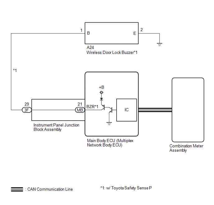
In some cases, wireless door lock control functions are normal but the hazard warning light and/or wireless door lock buzzer answer-back function*1 does not operate. In such cases, hazard warning light and wireless door lock buzzer*1 signal outputs from the main body ECU (multiplex network body ECU) may be malfunctioning.
- *1: w/ Toyota Safety Sense P
WIRING DIAGRAM
CAUTION / NOTICE / HINT
NOTICE:
- The wireless door lock control system and key reminder warning system
use the CAN communication system. Inspect the communication function by
following How to Proceed with Troubleshooting. Troubleshoot the wireless
door lock control system after confirming that the communication system
is functioning properly.
Click here
.gif)
- If the main body ECU (multiplex network body ECU) is replaced, refer
to Registration.
Click here
PROCEDURE
|
1. |
READ VALUE USING TECHSTREAM (Hazard Answer Back, Wireless Buzzer Resp, Wireless Buzzer Vol) |
(a) Connect the Techstream to the DLC3.
(b) Turn the engine switch on (IG).
(c) Turn the Techstream on.
(d) Enter the following menus: Customize Setting / Wireless Door Lock.
(e) Select the setting by referring to the table below.
Wireless Door Lock|
Tester Display |
Description |
Default |
Setting |
ECU |
|---|---|---|---|---|
|
Hazard Answer Back |
Function that flashes the hazard warning lights once when the doors are locked by wireless operation and twice when the doors are unlocked by wireless operation. |
ON |
0:OFF,1:ON |
Main body ECU (Multiplex network body ECU) |
|
Wireless Buzzer Resp |
Wireless door lock buzzer response*1 |
ON |
0:OFF,1:ON |
Main body ECU (Multiplex network body ECU) |
|
Wireless Buzzer Vol |
Wireless door lock buzzer volume*1 |
Level5 |
0000:Level7,0001:Level6,0010:Level5,0011:Level4,0100:Level3,0101:Level2,0110:Level1,0111:Level0 |
Main body ECU (Multiplex network body ECU) |
- *1: w/ Toyota Safety Sense P
|
Result |
Proceed to |
|---|---|
|
Both items are ON and except Level 0 |
A |
|
Either item is OFF or Level 0 |
B |
| B | .gif) |
PERFORM CUSTOMIZE FUNCTION
|
|
.gif)
|
2. |
CHECK WIRELESS DOOR LOCK CONTROL FUNCTIONS |
(a) Check the wireless door lock control function using the electrical key transmitter sub-assembly.
|
Result |
Proceed to |
|---|---|
|
Wireless door lock/unlock operates properly |
A |
|
Wireless door lock/unlock does not operate properly |
B |
| B | |
GO TO PROBLEM SYMPTOMS TABLE |
|
|
3. |
READ VALUE USING TECHSTREAM (FR Door Lock Pos, FL Door Lock Pos, RR-Door Lock Pos SW, RL-Door Lock Pos SW) |
(a) Connect the Techstream to the DLC3.
(b) Turn the engine switch on (IG).
(c) Turn the Techstream on.
(d) Enter the following menus: Body Electrical / Main Body / Data List.
(e) Read the Data List according to the display on the Techstream.
Body Electrical > Main Body > Data List|
Tester Display |
Measurement Item |
Range |
Normal Condition |
Diagnostic Note |
|---|---|---|---|---|
|
FR Door Lock Pos |
Front door RH unlock detection switch signal |
LOCK or UNLOCK |
LOCK: Front door RH locked UNLOCK: Front door RH unlocked |
- |
|
FL Door Lock Pos |
Front door LH unlock detection switch signal |
LOCK or UNLOCK |
LOCK: Front door LH locked UNLOCK: Front door LH unlocked |
- |
|
RR-Door Lock Pos SW |
Rear door RH unlock detection switch signal |
OFF or ON |
OFF: Rear door RH locked ON: Rear door RH unlocked |
- |
|
RL-Door Lock Pos SW |
Rear door LH unlock detection switch signal |
OFF or ON |
OFF: Rear door LH locked ON: Rear door LH unlocked |
- |
|
Tester Display |
|---|
|
FR Door Lock Pos |
|
FL Door Lock Pos |
|
RR-Door Lock Pos SW |
|
RL-Door Lock Pos SW |
OK:
The Techstream display changes correctly in response to the lock/unlock operation.
| NG | |
GO TO LIGHTING SYSTEM (Proceed to Door Unlock Detection Switch Circuit) |
|
|
4. |
CHECK WIRELESS ANSWER-BACK OPERATION |
(a) Check the wireless answer-back operation using the electrical key transmitter sub-assembly.
|
Result |
Proceed to |
|---|---|
|
Only wireless door lock buzzer answer-back does not occur (w/ Toyota Safety Sense P) |
A |
|
Only hazard warning light answer-back does not occur |
B |
| A | |
GO TO SMART KEY SYSTEM (for Entry Function) (Entry Exterior Alarm and Answer-back Buzzer do not Sound) |
|
|
5. |
CHECK HAZARD WARNING LIGHTS OPERATION |
(a) Check that the hazard warning lights blink when the hazard warning signal switch is pressed.
OK:
Hazard warning lights blink.
| OK | |
REPLACE MAIN BODY ECU (MULTIPLEX NETWORK BODY ECU) |
| NG | |
GO TO LIGHTING SYSTEM (Proceed to Hazard Warning Switch Circuit) |
 Wireless Door Lock Tuner Circuit Malfunction (B1242)
DESCRIPTION
The electrical key and TPMS receiver assembly is used to receive radio waves
related to the entry functions of the electrical key transmitter sub-assembly. The
certification ECU (smar ...

Other materials:
Toyota CH-R Service Manual > Supplemental Restraint Systems: Airbag Cut-off Indicator Light
Components
COMPONENTS
ILLUSTRATION
*1
CLOCK ASSEMBLY
*2
INSTRUMENT CLUSTER FINISH CENTER PANEL SUB-ASSEMBLY
Inspection
INSPECTION
PROCEDURE
1. INSPECT AIRBAG CUT-OFF INDICATOR LIGHT (CLOCK ASSEMBLY)
(a) Check illumination.
...
Toyota CH-R Service Manual > Lumbar Switch: Installation
INSTALLATION
CAUTION / NOTICE / HINT
CAUTION:
Be sure to read Precaution thoroughly before servicing.
Click here
Wear protective gloves. Sharp areas on the parts may injure your hands.
HINT:
Front lumbar power seat switch is available only on the driver side ...
Toyota C-HR (AX20) 2023-2026 Owner's Manual
Toyota CH-R Owners Manual
- For safety and security
- Instrument cluster
- Operation of each component
- Driving
- Interior features
- Maintenance and care
- When trouble arises
- Vehicle specifications
- For owners
Toyota CH-R Service Manual
- Introduction
- Maintenance
- Audio / Video
- Cellular Communication
- Navigation / Multi Info Display
- Park Assist / Monitoring
- Brake (front)
- Brake (rear)
- Brake Control / Dynamic Control Systems
- Brake System (other)
- Parking Brake
- Axle And Differential
- Drive Shaft / Propeller Shaft
- K114 Cvt
- 3zr-fae Battery / Charging
- Networking
- Power Distribution
- Power Assist Systems
- Steering Column
- Steering Gear / Linkage
- Alignment / Handling Diagnosis
- Front Suspension
- Rear Suspension
- Tire / Wheel
- Tire Pressure Monitoring
- Door / Hatch
- Exterior Panels / Trim
- Horn
- Lighting (ext)
- Mirror (ext)
- Window / Glass
- Wiper / Washer
- Door Lock
- Heating / Air Conditioning
- Interior Panels / Trim
- Lighting (int)
- Meter / Gauge / Display
- Mirror (int)
- Power Outlets (int)
- Pre-collision
- Seat
- Seat Belt
- Supplemental Restraint Systems
- Theft Deterrent / Keyless Entry

0.0087