Toyota CH-R Service Manual: Wireless Door Lock Tuner Circuit Malfunction (B1242)
DESCRIPTION
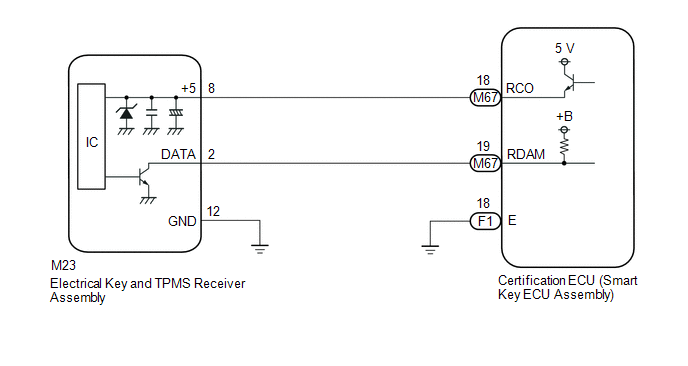
The electrical key and TPMS receiver assembly is used to receive radio waves related to the entry functions of the electrical key transmitter sub-assembly. The certification ECU (smart key ECU assembly) decodes the requested electrical key transmitter sub-assembly operation by identifying a key code based on the radio waves received via the electrical key and TPMS receiver assembly. The electrical key and TPMS receiver assembly receives a signal from the electrical key transmitter sub-assembly and sends signals to the main body ECU (multiplex network body ECU) through the certification ECU (smart key ECU assembly). (ex. If a door lock operation is requested, the certification ECU (smart key ECU assembly) sends a door lock command to the main body ECU (multiplex network body ECU)).
|
DTC No. |
Detection Item |
DTC Detection Condition |
Trouble Area |
|---|---|---|---|
|
B1242 |
Wireless Door Lock Tuner Circuit Malfunction |
|
|
WIRING DIAGRAM
CAUTION / NOTICE / HINT
NOTICE:
- When replacing or inspecting the electrical key and TPMS receiver assembly and wire harness, do not change the position or length of the wire harness. If the wire harness is too close to the electrical key and TPMS receiver assembly, the performance of the entry function and wireless function may be affected.
- This DTC is not stored within 10 seconds of the engine switch being turned from on (IG) to off.
- The wireless door lock control system uses the CAN communication system.
Inspect the communication function by following How to Proceed with Troubleshooting.
Troubleshoot the wireless door lock control system after confirming that
the communication system is functioning properly.
Click here
.gif)
- Before replacing the certification ECU (smart key ECU assembly), refer
to Registration.
Click here
- When replacing the electrical key and TPMS receiver assembly, read the
transmitter IDs (tire pressure warning system) stored in the old ECU using
the Techstream and write them down before removal.
Click here
- It is necessary to perform initialization (Click here
) after registration (Click here
) of the transmitter IDs into the electrical key and TPMS receiver assembly
if the electrical key and TPMS receiver assembly has been replaced.
PROCEDURE
|
1. |
CHECK CERTIFICATION ECU (SMART KEY ECU ASSEMBLY) |
(a) Disconnect the M23 electrical key and TPMS receiver assembly connector.
|
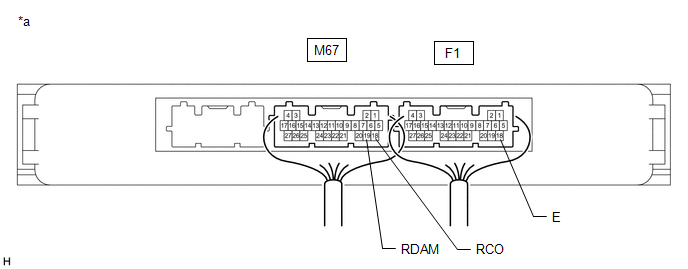
*a |
Component with harness connected (Certification ECU (Smart Key ECU Assembly)) |
- |
- |
(b) Measure the voltage and resistance and check for pulses according to the value(s) in the table below.
Standard Voltage:
|
Tester Connection |
Condition |
Specified Condition |
|---|---|---|
|
M67-19 (RDAM) - F1-18 (E) |
Engine switch off |
11 to 14 V |
|
M67-18 (RCO) - F1-18 (E) |
always |
Below 1 V → 4.5 to 5.5 V pulse generation at regular intervals |
Standard Resistance:
|
Tester Connection |
Condition |
Specified Condition |
|---|---|---|
|
F1-18 (E) - Body ground |
Always |
Below 1 Ω |
| OK | .gif) |
REPLACE ELECTRICAL KEY AND TPMS RECEIVER ASSEMBLY
|
|
.gif)
|
2. |
CHECK HARNESS AND CONNECTOR (ELECTRICAL KEY AND TPMS RECEIVER ASSEMBLY - CERTIFICATION ECU (SMART KEY ECU ASSEMBLY)) |
(a) Disconnect the F1 and M67 certification ECU (smart key ECU assembly) connectors.
(b) Measure the resistance according to the value(s) in the table below.
Standard Resistance:
|
Tester Connection |
Condition |
Specified Condition |
|---|---|---|
|
M67-19 (RDAM) - M23-2 (DATA) |
Always |
Below 1 Ω |
|
M67-18 (RCO) - M23-8 (+5) |
Always |
Below 1 Ω |
|
M23-12 (GND) - Body ground |
Always |
Below 1 Ω |
|
M23-2 (DATA) or M67-19 (RDAM) - Body ground |
Always |
10 kΩ or higher |
|
M23-8 (+5) or M67-18 (RCO) - Body ground |
Always |
10 kΩ or higher |
| OK | |
REPLACE CERTIFICATION ECU (SMART KEY ECU ASSEMBLY) |
| NG | |
REPAIR OR REPLACE HARNESS OR CONNECTOR |
 Diagnostic Trouble Code Chart
DIAGNOSTIC TROUBLE CODE CHART
Wireless Door Lock Control System
DTC No.
Detection Item
Link
B1242
Wireless Door Lock Tuner Circuit Malfun ...
 No Answer-Back
DESCRIPTION
In some cases, wireless door lock control functions are normal but the hazard
warning light and/or wireless door lock buzzer answer-back function*1 does not operate.
In such cases, ha ...
Other materials:
Toyota CH-R Service Manual > Theft Deterrent System: Terminals Of Ecu
TERMINALS OF ECU
CHECK INSTRUMENT PANEL JUNCTION BLOCK ASSEMBLY AND MAIN BODY ECU (MULTIPLEX NETWORK
BODY ECU)
*A
Main Body ECU (Multiplex Network Body ECU) with 2 Connectors
-
-
*1
Main Body ECU (Multiplex Network Body EC ...
Toyota CH-R Service Manual > Wiper / Washer: Rear Wiper Rubber
Components
COMPONENTS
ILLUSTRATION
*1
REAR WIPER BLADE
*2
REAR WIPER RUBBER
*3
REAR WIPER RUBBER BACKING PLATE
-
-
...
Toyota C-HR (AX20) 2023-2026 Owner's Manual
Toyota CH-R Owners Manual
- For safety and security
- Instrument cluster
- Operation of each component
- Driving
- Interior features
- Maintenance and care
- When trouble arises
- Vehicle specifications
- For owners
Toyota CH-R Service Manual
- Introduction
- Maintenance
- Audio / Video
- Cellular Communication
- Navigation / Multi Info Display
- Park Assist / Monitoring
- Brake (front)
- Brake (rear)
- Brake Control / Dynamic Control Systems
- Brake System (other)
- Parking Brake
- Axle And Differential
- Drive Shaft / Propeller Shaft
- K114 Cvt
- 3zr-fae Battery / Charging
- Networking
- Power Distribution
- Power Assist Systems
- Steering Column
- Steering Gear / Linkage
- Alignment / Handling Diagnosis
- Front Suspension
- Rear Suspension
- Tire / Wheel
- Tire Pressure Monitoring
- Door / Hatch
- Exterior Panels / Trim
- Horn
- Lighting (ext)
- Mirror (ext)
- Window / Glass
- Wiper / Washer
- Door Lock
- Heating / Air Conditioning
- Interior Panels / Trim
- Lighting (int)
- Meter / Gauge / Display
- Mirror (int)
- Power Outlets (int)
- Pre-collision
- Seat
- Seat Belt
- Supplemental Restraint Systems
- Theft Deterrent / Keyless Entry

0.0089