Toyota CH-R Service Manual: 3zr-fae Air Cleaner Filter Element
Components
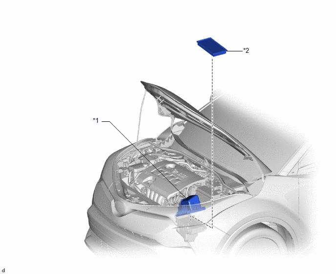
COMPONENTS
ILLUSTRATION
|
*1 |
AIR CLEANER CAP SUB-ASSEMBLY |
*2 |
AIR CLEANER FILTER ELEMENT SUB-ASSEMBLY |
Removal
REMOVAL
PROCEDURE
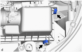
1. SEPARATE AIR CLEANER CAP SUB-ASSEMBLY
|
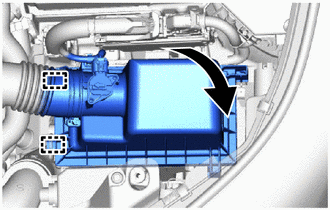
(a) Disconnect the 2 clamp hooks from the air cleaner cap sub-assembly. |
|
|
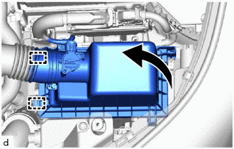
(b) Disengage the 2 guides and separate the air cleaner cap sub-assembly together with air cleaner hose assembly from the air cleaner case sub-assembly. |
|
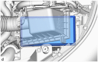
2. REMOVE AIR CLEANER FILTER ELEMENT SUB-ASSEMBLY
|
(a) Remove the air cleaner filter element sub-assembly from the air cleaner case sub-assembly. NOTICE: Do not allow foreign matter to enter the air cleaner case sub-assembly. |
|
3. INSPECT AIR CLEANER FILTER ELEMENT SUB-ASSEMBLY
HINT:
This procedure is only performed when the air cleaner filter element sub-assembly will be reused.
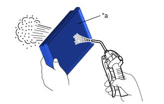
(a) Check whether the air cleaner filter element sub-assembly is dirty or clogged.
|
(b) If the air cleaner filter element sub-assembly is dirty or has foreign matter adhered to it, clean the air cleaner filter element sub-assembly with compressed air. NOTICE: When cleaning the air cleaner filter element sub-assembly, blow the compressed air from the intake downstream side (from the throttle body assembly side). If the air cleaner filter element sub-assembly is still extremely dirty after cleaning it, replace the air cleaner filter element sub-assembly with a new one. |
|
Installation
INSTALLATION
PROCEDURE
1. INSTALL AIR CLEANER FILTER ELEMENT SUB-ASSEMBLY
(a) Check that the inside of the air cleaner case sub-assembly does not have dirt or deposits, and clean them away if they are present.
(b) Install the air cleaner filter element sub-assembly to the air cleaner case sub-assembly.
2. INSTALL AIR CLEANER CAP SUB-ASSEMBLY
|
(a) Engage the 2 guides and connect the air cleaner cap sub-assembly together with air cleaner hose assembly to the air cleaner case sub-assembly. |
|
(b) Secure the air cleaner cap sub-assembly with the 2 clamp hooks.
 Maintenance
...
 3zr-fae Battery
...
Other materials:
Toyota CH-R Service Manual > Repair Instruction: Initialization
INITIALIZATION
PROCEDURES NECESSARY WHEN BATTERY TERMINAL IS DISCONNECTED/RECONNECTED
Necessary Procedures
Effect/Inoperative Function when Necessary Procedures not Performed
Link
Initialize back door lock
Power door lock control system
...
Toyota CH-R Service Manual > Smart Key System(for Entry Function): Entry Exterior Alarm does not Sound
DESCRIPTION
The smart key system (for Entry Function) uses the wireless door lock buzzer
to perform various vehicle exterior warnings. When the conditions of each warning
are met, the certification ECU (smart key ECU assembly) sends a buzzer activation
request signal to the main body ECU (mul ...
Toyota C-HR (AX20) 2023-2026 Owner's Manual
Toyota CH-R Owners Manual
- For safety and security
- Instrument cluster
- Operation of each component
- Driving
- Interior features
- Maintenance and care
- When trouble arises
- Vehicle specifications
- For owners
Toyota CH-R Service Manual
- Introduction
- Maintenance
- Audio / Video
- Cellular Communication
- Navigation / Multi Info Display
- Park Assist / Monitoring
- Brake (front)
- Brake (rear)
- Brake Control / Dynamic Control Systems
- Brake System (other)
- Parking Brake
- Axle And Differential
- Drive Shaft / Propeller Shaft
- K114 Cvt
- 3zr-fae Battery / Charging
- Networking
- Power Distribution
- Power Assist Systems
- Steering Column
- Steering Gear / Linkage
- Alignment / Handling Diagnosis
- Front Suspension
- Rear Suspension
- Tire / Wheel
- Tire Pressure Monitoring
- Door / Hatch
- Exterior Panels / Trim
- Horn
- Lighting (ext)
- Mirror (ext)
- Window / Glass
- Wiper / Washer
- Door Lock
- Heating / Air Conditioning
- Interior Panels / Trim
- Lighting (int)
- Meter / Gauge / Display
- Mirror (int)
- Power Outlets (int)
- Pre-collision
- Seat
- Seat Belt
- Supplemental Restraint Systems
- Theft Deterrent / Keyless Entry

0.0065