Toyota CH-R Service Manual: Performance Decline of Brake Function (C1441)
DESCRIPTION
The skid control ECU judges brake failure conditions have occurred based on signals from the brake pedal load sensing switch and master cylinder pressure sensor.
NOTICE:
Do not intentionally stop the engine when driving. Even when no malfunction has occurred in the brake system, DTC C1441 will be stored when it is judged that a failure has occurred in the brake system due to a reduction in vacuum.
DTCs may be stored if one of the following occurs:
- The brake pedal load sensing switch is malfunctioning (deviation in characteristics).
- The brake pedal is depressed when moving the vehicle with the engine not running and the ignition switch ON.
- Bleeding is performed with the engine running or the ignition switch ON.
- The accelerator and brake pedals depressed simultaneously.*
HINT:
*: The skid control ECU may store this DTC upon judging that a stuck on malfunction has occurred when the accelerator pedal and brake pedal are depressed simultaneously. However, this does not indicate a malfunction.
|
DTC No. |
Detection Item |
DTC Detection Condition |
Trouble Area |
|---|---|---|---|
|
C1441 |
Performance Decline of Brake Function |
When the brake pedal load sensing switch and master cylinder pressure sensor are functioning normally and the brake pedal load sensing switch is judged as on, the pressure signal from the master cylinder pressure sensor does not indicate an increase. |
|
PROCEDURE
|
1. |
CHECK ACCELERATOR PEDAL AND BRAKE PEDAL OPERATION |
(a) Interview the customer to check if the pedals were depressed simultaneously while driving or braking.
OK:
The pedals were not depressed simultaneously.
HINT:
The skid control ECU may store this DTC upon judging that a stuck on malfunction has occurred when the accelerator pedal and brake pedal are depressed simultaneously. If the pedals were depressed simultaneously, clear the DTC because it is not a malfunction.
| NG | .gif) |
END |
|
.gif)
|
2. |
CHECK DTC AND FREEZE FRAME DATA |
(a) Check and record DTCs and Freeze Frame Data (Click here
.gif) for Check DTCs and Click here
for Freeze Frame Data).
for Check DTCs and Click here
for Freeze Frame Data).
HINT:
- Read Freeze Frame Data at the time DTC C1441 was stored, go to operation history and confirm the operating conditions.
- When reading Freeze Frame Data to confirm operating conditions, the following items can be confirmed: "F# or R# Wheel Speed", "Vehicle Speed", "Real Engine Torque" and "Accelerator Opening Angle %".
|
|
3. |
CLEAR DTC |
(a) Clear the DTCs and Freeze Frame Data (Click here
for Clear DTCs and Click here
for Freeze Frame Data).
|
|
4. |
CHECK BRAKE PEDAL OPERATION |
(a) Based on the customer problem analysis, confirm the brake pedal condition at the time the brake pedal was operated.
|
Result |
Proceed to |
|---|---|
|
The brake pedal is hard to depress. |
A |
|
The brake pedal is extremely easy to depress. |
B |
|
Neither of the above conditions. (Problem symptom does not occur.) |
C |
| B | |
GO TO STEP 6 |
| C | |
GO TO STEP 7 |
|
|
5. |
CHECK BRAKE BOOSTER ASSEMBLY |
(a) Check the brake booster assembly.
Click here
|
Result |
Proceed to |
|---|---|
|
The brake booster assembly is abnormal. |
A |
|
The brake booster assembly is normal. |
B |
HINT:
If the result shows that the brake booster assembly is defective, check the related components such as the brake booster, brake vacuum check valve, vacuum warning switch assembly (for 6AR-FSE), check valve grommet, brake booster gasket, vacuum hose and intake system for vacuum leaks or clogs.
| A | |
INSPECT RELATED COMPONENTS (FOR VACUUM LEAKS OR CLOGS) |
| B | |
GO TO STEP 7 |
|
6. |
CHECK BRAKE FLUID LEVEL |
(a) Check that the brake fluid level is sufficient.
HINT:
- If the fluid level is low, check for a fluid leaks, and repair as necessary.
- Check for brake fluid leakage (brake master cylinder, brake line, flexible hose, brake actuator, wheel cylinders, etc.).
|
Result |
Proceed to |
|---|---|
|
Brake fluid level is not sufficient. |
A |
|
Brake fluid level is sufficient. |
B |
HINT:
If brake fluid leaks are not found in components such as the brake master cylinder, brake line, flexible hose, brake actuator or wheel cylinders but the fluid level has become lower, the brake master cylinder may be leaking internally. Therefore, replace the brake master cylinder and check brake pedal operation again.
| A | |
CHECK AND REPLACE BRAKE FLUID LEAKS |
|
|
7. |
RECONFIRM DTC |
(a) Clear the DTCs.
Click here
(b) Start the engine.
(c) Perform a road test.
NOTICE:
Do not intentionally stop the engine when driving. DTC C1441 will be stored if the brake pedal is depressed when moving the vehicle with the engine not running and the ignition switch ON.
(d) Check if the same DTC is recorded.
Click here
|
Result |
Proceed to |
|---|---|
|
DTC C1441 is not output. |
A |
|
DTCs C1441 and other DTC are output. |
B |
|
Only DTC C1441 is output. |
C |
HINT:
- If DTC C1441 and other DTCs are output simultaneously, the other DTCs may have caused the engine to malfunction, resulting in DTC C1441 to be output. Read Freeze Frame Data to confirm malfunctioning parts and repair the applicable part.
- When reading Freeze Frame Data to confirm malfunctioning parts, the following items can be confirmed: "F# or R# Wheel Speed", "Vehicle Speed", "Real Engine Torque" and "Accelerator Opening Angle %".
| A | |
END |
| B | |
CHECK AND REPLACE APPLICABLE PART |
|
|
8. |
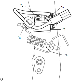
CHECK BRAKE PEDAL SUPPORT ASSEMBLY |
|
(a) Check that the matchmarks on the adjustment part of the brake pedal load sensing switch are aligned with the matchmarks on the brackets, nuts, adjusting screw, etc. OK: The matchmarks on the adjustment part of the brake pedal load sensing switch are aligned with the matchmarks on the brackets, nuts, adjusting screw, etc. |
|
| OK | |
REPLACE BRAKE ACTUATOR ASSEMBLY |
| NG | |
REPLACE BRAKE PEDAL SUPPORT ASSEMBLY |
 Steering Angle Sensor Initialization Incomplete (C1439,C1445)
DESCRIPTION
The skid control ECU (brake actuator assembly) acquires the steering angle sensor
zero point every time the ignition switch is turned to ON and the vehicle is driven
at 50 km/h (31 mp ...
 Yaw Rate Sensor Output Value (C1448)
DESCRIPTION
The yaw rate and acceleration sensor is built into the airbag sensor assembly.
The skid control ECU receives signals from the yaw rate and acceleration sensor
(airbag sensor assembly) ...
Other materials:
Toyota CH-R Service Manual > Audio And Visual System(for Radio Receiver Type): Noise Occurs
PROCEDURE
1.
NOISE CONDITION
(a) Check from which direction the noise comes (front left or right, rear left
or right).
OK:
The location of the noise source can be determined.
NG
GO TO STEP 3
OK
...
Toyota CH-R Service Manual > Audio And Visual System(for Radio And Display Type): Data List / Active Test
DATA LIST / ACTIVE TEST
DATA LIST
NOTICE:
In the table below, the values listed under "Normal Condition" are reference
values. Do not depend solely on these reference values when deciding whether a part
is faulty or not.
HINT:
Using the Techstream to read the Data List allows the ...
Toyota C-HR (AX20) 2023-2026 Owner's Manual
Toyota CH-R Owners Manual
- For safety and security
- Instrument cluster
- Operation of each component
- Driving
- Interior features
- Maintenance and care
- When trouble arises
- Vehicle specifications
- For owners
Toyota CH-R Service Manual
- Introduction
- Maintenance
- Audio / Video
- Cellular Communication
- Navigation / Multi Info Display
- Park Assist / Monitoring
- Brake (front)
- Brake (rear)
- Brake Control / Dynamic Control Systems
- Brake System (other)
- Parking Brake
- Axle And Differential
- Drive Shaft / Propeller Shaft
- K114 Cvt
- 3zr-fae Battery / Charging
- Networking
- Power Distribution
- Power Assist Systems
- Steering Column
- Steering Gear / Linkage
- Alignment / Handling Diagnosis
- Front Suspension
- Rear Suspension
- Tire / Wheel
- Tire Pressure Monitoring
- Door / Hatch
- Exterior Panels / Trim
- Horn
- Lighting (ext)
- Mirror (ext)
- Window / Glass
- Wiper / Washer
- Door Lock
- Heating / Air Conditioning
- Interior Panels / Trim
- Lighting (int)
- Meter / Gauge / Display
- Mirror (int)
- Power Outlets (int)
- Pre-collision
- Seat
- Seat Belt
- Supplemental Restraint Systems
- Theft Deterrent / Keyless Entry

0.0081