Toyota CH-R Service Manual: Terminals Of Ecu
TERMINALS OF ECU
CHECK INSTRUMENT PANEL JUNCTION BLOCK ASSEMBLY AND MAIN BODY ECU (MULTIPLEX NETWORK BODY ECU)
.png)
|
*A |
Main Body ECU (Multiplex Network Body ECU) with 2 Connectors |
- |
- |
|
*1 |
Main Body ECU (Multiplex Network Body ECU) |
- |
- |
|
*a |
2 Connectors |
- |
- |
.png)
|
*A |
Main Body ECU (Multiplex Network Body ECU) with 1 Connector |
- |
- |
|
*1 |
Main Body ECU (Multiplex Network Body ECU) |
- |
- |
|
*a |
1 Connector |
- |
- |
(a) Remove the main body ECU (multiplex network body ECU) from the instrument panel junction block assembly.
Click here
.gif)
(b) Reconnect the instrument panel junction block assembly connectors.
(c) Measure the voltage and resistance according to the value(s) in the table below.
|
Terminal No. (Symbol) |
Wiring Color |
Terminal Description |
Condition |
Specified Condition |
|---|---|---|---|---|
|
MB-11 (GND1) - Body ground |
- |
Ground |
Always |
Below 1 Ω |
|
MB-30 (ACC) - Body ground |
- |
ACC power supply |
Engine switch on (ACC) |
11 to 14 V |
|
MB-30 (ACC) - Body ground |
- |
ACC power supply |
Engine switch off |
Below 1 V |
|
MB-31 (BECU) - Body ground |
- |
Battery power supply |
Always |
11 to 14 V |
|
MB-32 (IG) - Body ground |
- |
IG power supply |
Engine switch on (IG) |
11 to 14 V |
|
MB-32 (IG) - Body ground |
- |
IG power supply |
Engine switch off |
Below 1 V |
(d) Install the main body ECU (multiplex network body ECU) to the instrument panel junction block assembly.
Click here
(e) Measure the voltage and check for pulses according to the value(s) in the table below.
|
Terminal No. (Symbol) |
Wiring Color |
Terminal Description |
Condition |
Specified Condition |
|---|---|---|---|---|
|
3D-14 (LSR) - Body ground |
LG - Body ground |
Rear door LH/RH unlock detection switch input |
Rear door LH or RH unlocked |
Below 1 V |
|
3D-14 (LSR) - Body ground |
LG - Body ground |
Rear door LH/RH unlock detection switch input |
Rear door LH and RH locked |
Pulse generation |
|
3D-13 (LSFL) - Body ground |
B - Body ground |
Front door LH unlock detection switch input |
Front door LH unlocked |
Below 1 V |
|
3D-13 (LSFL) - Body ground |
B - Body ground |
Front door LH unlock detection switch input |
Front door LH locked |
Pulse generation |
|
3D-12 (LSFR) - Body ground |
GR - Body ground |
Front door RH unlock detection switch input |
Front door RH unlocked |
Below 1 V |
|
3D-12 (LSFR) - Body ground |
GR - Body ground |
Front door RH unlock detection switch input |
Front door RH locked |
Pulse generation |
|
F15-2 (UL3) - Body ground |
L - Body ground |
Driver door key-linked unlock input |
Driver door key cylinder in neutral position → on (unlock) |
Pulse generation → Below 1 V |
|
F15-29 (L2) - Body ground |
G - Body ground |
Driver door key-linked lock input |
Driver door key cylinder in neutral position → on (lock) |
Pulse generation → Below 1 V |
|
F15-6 (FLCY) - Body ground |
R - Body ground |
Front door courtesy light switch (for LH) input |
Front door LH open |
Below 1 V |
|
F15-6 (FLCY) - Body ground |
R - Body ground |
Front door courtesy light switch (for LH) input |
Front door LH closed |
Pulse generation |
|
F15-27 (FRCY) - Body ground |
BR - Body ground |
Front door courtesy light switch (for RH) input |
Front door RH open |
Below 1 V |
|
F15-27 (FRCY) - Body ground |
BR - Body ground |
Front door courtesy light switch (for RH) input |
Front door RH closed |
Pulse generation |
|
3H-24 (LCTY) - Body ground |
BR - Body ground |
Rear door courtesy light switch (for LH) input |
Rear door LH open |
Below 1 V |
|
3H-24 (LCTY) - Body ground |
BR - Body ground |
Rear door courtesy light switch (for LH) input |
Rear door LH closed |
Pulse generation |
|
3A-31 (RCTY) - Body ground |
BR - Body ground |
Rear door courtesy light switch (for RH) input |
Rear door RH open |
Below 1 V |
|
3A-31 (RCTY) - Body ground |
BR - Body ground |
Rear door courtesy light switch (for RH) input |
Rear door RH closed |
Pulse generation |
|
3H-34 (BCTY) - Body ground |
SB - Body ground |
Back door courtesy light switch input |
Back door open |
Below 1 V |
|
3H-34 (BCTY) - Body ground |
SB - Body ground |
Back door courtesy light switch input |
Back door closed |
Pulse generation |
|
3H-20 (TR+) - Body ground |
Y - Body ground |
Back door lock motor drive output |
Back door closed → open |
Below 1 V → 11 to 14 V → Below 1 V |
|
3H-8 (ACT-) - Body ground |
LA-B - Body ground |
Door lock motor unlock drive output |
Door control switch or driver door key cylinder off → on (unlock) |
Below 1 V → 11 to 14 V → Below 1 V |
|
3H-9 (ACT-) - Body ground |
B - Body ground |
Door lock motor unlock drive output |
Door control switch or driver door key cylinder off → on (unlock) |
Below 1 V → 11 to 14 V → Below 1 V |
|
3H-18 (ACT+) - Body ground |
R - Body ground |
Door lock motor lock drive output |
Door control switch or driver door key cylinder off → on (lock) |
Below 1 V → 11 to 14 V → Below 1 V |
|
3H-6 (ACT+) - Body ground |
R - Body ground |
Door lock motor lock drive output |
Door control switch or driver door key cylinder off → on (lock) |
Below 1 V → 11 to 14 V → Below 1 V |
|
3D-4 (ACTD) - Body ground |
B - Body ground |
Door lock motor unlock drive output |
Door control switch or driver door key cylinder off → on (unlock) |
Below 1 V → 11 to 14 V → Below 1 V |
|
3F-29 (BZR) - Body ground |
L - Body ground |
Wireless door lock buzzer signal |
Wireless door lock buzzer off |
Below 1 V |
|
3F-29 (BZR) - Body ground |
L - Body ground |
Wireless door lock buzzer signal |
Wireless door lock buzzer on |
Pulse generation |
CHECK CERTIFICATION ECU (SMART KEY ECU ASSEMBLY)
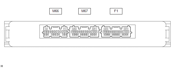
(a) Disconnect the F1 certification ECU (smart key ECU assembly) connector.
(b) Measure the voltage and resistance according to the value(s) in the table below.
|
Terminal No. (Symbol) |
Wiring Color |
Terminal Description |
Condition |
Specified Condition |
|---|---|---|---|---|
|
F1-4 (+B) - Body ground |
L - Body ground |
Battery power supply |
Always |
11 to 14 V |
|
F1-18 (E) - Body ground |
W-B - Body ground |
Ground |
Always |
Below 1 Ω |
(c) Reconnect the F1 certification ECU (smart key ECU assembly) connector.
(d) Measure the voltage and check for pulses according to the value(s) in the table below.
|
Terminal No. (Symbol) |
Wiring Color |
Terminal Description |
Condition |
Specified Condition |
|---|---|---|---|---|
|
M67-18 (RCO) - F1-18 (E) |
LG - W-B |
Output to electrical key and TPMS receiver assembly (Power supply for electrical key and TPMS receiver assembly. Certification ECU (smart key ECU assembly) outputs 5 V when receiver starts operating.) |
Procedure:
|
Below 1 V → 4.5 to 5.5 V |
|
M67-20 (CSEL) - F1-18 (E) |
V - W-B |
Communication channel switching circuit |
Procedure:
|
No pulse generation → Pulse generation |
|
M67-19 (RDAM) - F1-18 (E) |
GR - W-B |
Electrical key and TPMS receiver assembly communication circuit |
Procedure:
|
11 to 14 pulse generation at regular intervals → Pulse generation |
 Diagnosis System
DIAGNOSIS SYSTEM
DESCRIPTION
The main body ECU (multiplex network body ECU) stores DTCs when malfunctions
occur.
The diagnostic system allows for reading of the DTCs from the DLC3.
Use the Techs ...
 Dtc Check / Clear
DTC CHECK / CLEAR
CHECK DTC
(a) Connect the Techstream to the DLC3.
(b) Turn the engine switch on (IG).
(c) Turn the Techstream on.
(d) Enter the following menus: Body Electrical / Smart Key / Tr ...
Other materials:
Toyota CH-R Service Manual > Smart Key System(for Start Function): ACC Monitor Malfunction (B2274)
DESCRIPTION
This DTC is stored when a malfunction in the ACC output circuit is detected.
The ACC output circuit is the circuit between terminal ACCD of the certification
ECU (smart key ECU assembly) and the ACC relay.
DTC No.
Detection Item
DTC Detection Condit ...
Toyota CH-R Service Manual > Fuel Lid Opener Switch: Inspection
INSPECTION
PROCEDURE
1. INSPECT FUEL LID OPENER SWITCH
(a) Check the resistance.
(1) Measure the resistance according to the value(s) in the table below.
Standard Resistance:
Tester Connection
Switch Condition
Specified Condi ...
Toyota C-HR (AX20) 2023-2026 Owner's Manual
Toyota CH-R Owners Manual
- For safety and security
- Instrument cluster
- Operation of each component
- Driving
- Interior features
- Maintenance and care
- When trouble arises
- Vehicle specifications
- For owners
Toyota CH-R Service Manual
- Introduction
- Maintenance
- Audio / Video
- Cellular Communication
- Navigation / Multi Info Display
- Park Assist / Monitoring
- Brake (front)
- Brake (rear)
- Brake Control / Dynamic Control Systems
- Brake System (other)
- Parking Brake
- Axle And Differential
- Drive Shaft / Propeller Shaft
- K114 Cvt
- 3zr-fae Battery / Charging
- Networking
- Power Distribution
- Power Assist Systems
- Steering Column
- Steering Gear / Linkage
- Alignment / Handling Diagnosis
- Front Suspension
- Rear Suspension
- Tire / Wheel
- Tire Pressure Monitoring
- Door / Hatch
- Exterior Panels / Trim
- Horn
- Lighting (ext)
- Mirror (ext)
- Window / Glass
- Wiper / Washer
- Door Lock
- Heating / Air Conditioning
- Interior Panels / Trim
- Lighting (int)
- Meter / Gauge / Display
- Mirror (int)
- Power Outlets (int)
- Pre-collision
- Seat
- Seat Belt
- Supplemental Restraint Systems
- Theft Deterrent / Keyless Entry

0.0077