Toyota CH-R Service Manual: Diagnosis System
DIAGNOSIS SYSTEM
DESCRIPTION
The main body ECU (multiplex network body ECU) stores DTCs when malfunctions occur.
The diagnostic system allows for reading of the DTCs from the DLC3.
Use the Techstream to check for malfunctions and perform repairs.
CHECK DLC3
(a) Check the DLC3.
Click here
.gif)
INSPECT BATTERY VOLTAGE
(a) Measure the vehicle battery voltage.
Standard Voltage:
11 to 14 V
If the voltage is below 11 V, recharge or replace the battery.
SELF-DIAGNOSTIC MODE (USING Techstream)
(a) Connect the Techstream to the DLC3.
(b) Turn the engine switch on (IG).
(c) Turn the Techstream on.
(d) Enter the following menus: Body Electrical / Smart Key / Utility / Wireless Door Lock Diagnosis Mode.
Body Electrical > Smart Key > Utility|
Tester Display |
|---|
|
Wireless Door Lock Diagnosis Mode |
(e) Proceed to the next step in accordance with the prompts on the Techstream screen.
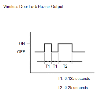
(f) Check that the system has switched to self-diagnostic mode by checking the wireless door lock buzzer output pattern.
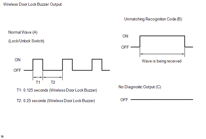
(g) Check the diagnostic output when an electrical key transmitter sub-assembly switch is pressed. The diagnostic outputs can be checked by the wireless door lock buzzer pattern.
 Result
|
Wireless Door Lock Buzzer Output |
Suspected Area |
|---|---|
|
A |
Normal (No malfunction) |
|
B |
Register electrical key transmitter sub-assembly |
|
C |
Wave interference or malfunction of a related component |
 Problem Symptoms Table
PROBLEM SYMPTOMS TABLE
HINT:
Use the table below to help determine the cause of problem symptoms.
If multiple suspected areas are listed, the potential causes of the symptoms
are lis ...
 Terminals Of Ecu
TERMINALS OF ECU
CHECK INSTRUMENT PANEL JUNCTION BLOCK ASSEMBLY AND MAIN BODY ECU (MULTIPLEX NETWORK
BODY ECU)
*A
Main Body ECU (Multiplex Network Body ECU) with 2 Connecto ...
Other materials:
Toyota CH-R Service Manual > Lighting System: Operation Check
OPERATION CHECK
AUTOMATIC LIGHT CONTROL SYSTEM OPERATION CHECK
(a) Turn the ignition switch to ON.
(b) Turn the light control switch to the AUTO position.
(c) Cover the automatic light control sensor.
(d) Check that the taillights and low beam headlights come on.
(e) Uncover the automatic ligh ...
Toyota CH-R Service Manual > Front Seat Side Airbag Assembly: Disposal
DISPOSAL
CAUTION / NOTICE / HINT
CAUTION:
Before performing pre-disposal deployment of any SRS part, review and closely
follow all applicable environmental and hazardous material regulations. Pre-disposal
deployment may be considered hazardous material treatment.
PROCEDURE
1. PRECAUTION
...
Toyota C-HR (AX20) 2023-2026 Owner's Manual
Toyota CH-R Owners Manual
- For safety and security
- Instrument cluster
- Operation of each component
- Driving
- Interior features
- Maintenance and care
- When trouble arises
- Vehicle specifications
- For owners
Toyota CH-R Service Manual
- Introduction
- Maintenance
- Audio / Video
- Cellular Communication
- Navigation / Multi Info Display
- Park Assist / Monitoring
- Brake (front)
- Brake (rear)
- Brake Control / Dynamic Control Systems
- Brake System (other)
- Parking Brake
- Axle And Differential
- Drive Shaft / Propeller Shaft
- K114 Cvt
- 3zr-fae Battery / Charging
- Networking
- Power Distribution
- Power Assist Systems
- Steering Column
- Steering Gear / Linkage
- Alignment / Handling Diagnosis
- Front Suspension
- Rear Suspension
- Tire / Wheel
- Tire Pressure Monitoring
- Door / Hatch
- Exterior Panels / Trim
- Horn
- Lighting (ext)
- Mirror (ext)
- Window / Glass
- Wiper / Washer
- Door Lock
- Heating / Air Conditioning
- Interior Panels / Trim
- Lighting (int)
- Meter / Gauge / Display
- Mirror (int)
- Power Outlets (int)
- Pre-collision
- Seat
- Seat Belt
- Supplemental Restraint Systems
- Theft Deterrent / Keyless Entry

0.0082