Toyota CH-R Service Manual: All Doors LOCK/UNLOCK Functions do not Operate Via Door Control Switch or Door Key Cylinder
DESCRIPTION
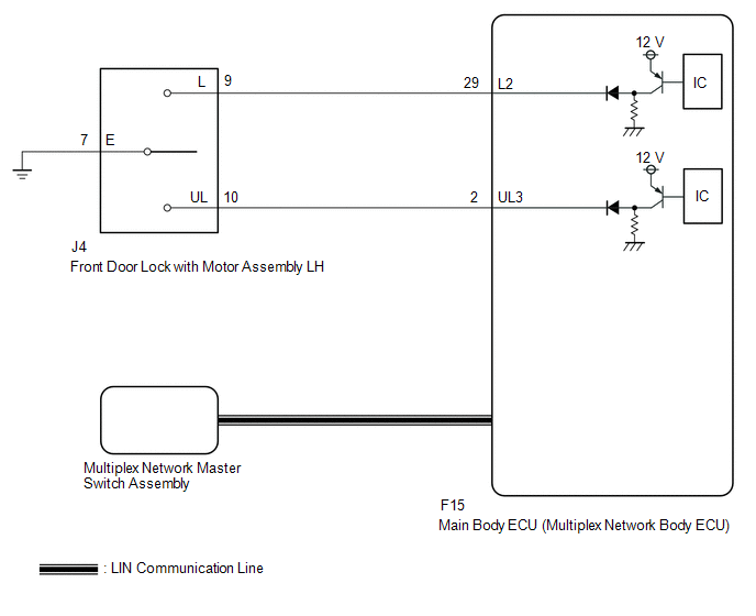
The main body ECU (multiplex network body ECU) receives switch signals from the multiplex network master switch assembly and driver door key cylinder lock or unlock switch signals from the front door lock with motor assembly LH. The main body ECU (multiplex network body ECU) activates the door lock motor on each door according to these signals.
WIRING DIAGRAM
CAUTION / NOTICE / HINT
NOTICE:
- Before replacing the main body ECU (multiplex network body ECU), refer
to Registration*.
Click here
.gif)
- *: w/ Smart Key System
- The power door lock control system uses the LIN communication system.
Inspect the communication function by following How to Proceed with Troubleshooting.
Troubleshoot the power door lock control system after confirming that the
communication systems are functioning properly.
Click here
PROCEDURE
|
1. |
CHECK DOOR LOCK OPERATION |
(a) Check door lock operation.
Click here
|
Result |
Proceed to |
|---|---|
|
All doors cannot be locked by multiplex network master switch assembly |
A |
|
All doors cannot be locked by driver door key cylinder |
B |
| B | .gif) |
GO TO STEP 5 |
|
.gif)
|
2. |
CHECK FOR DTC (LIN COMMUNICATION SYSTEM) |
(a) Clear the DTCs.
Click here
(b) Recheck for DTCs.
Body Electrical > Main Body > Trouble CodesOK:
DTC B1206 is not output.
| NG | |
GO TO LIN COMMUNICATION SYSTEM (DTC B1206) |
|
|
3. |
REPLACE MULTIPLEX NETWORK MASTER SWITCH ASSEMBLY |
(a) Replace the multiplex network master switch assembly.
Click here
|
|
4. |
CHECK DOOR LOCK OPERATION |
(a) Check that all doors can be locked and unlocked by the multiplex network master switch assembly.
Click here
OK:
All doors can be locked and unlocked by the multiplex network master switch assembly.
| OK | |
END (MULTIPLEX NETWORK MASTER SWITCH ASSEMBLY WAS DEFECTIVE) |
| NG | |
REPLACE MAIN BODY ECU (MULTIPLEX NETWORK BODY ECU)
|
|
5. |
READ VALUE USING TECHSTREAM (Door Key SW-Lock, D Door Key SW-UL) |
(a) Connect the Techstream to the DLC3.
(b) Turn the ignition switch to ON.
(c) Turn the Techstream on.
(d) Enter the following menus: Body Electrical / Main Body / Data List.
(e) Read the Data List according to the display on the Techstream.
Body Electrical > Main Body > Data List|
Tester Display |
Measurement Item |
Range |
Normal Condition |
Diagnostic Note |
|---|---|---|---|---|
|
Door Key SW-Lock |
Driver door key-linked lock / unlock switch lock signal |
OFF or ON |
OFF: Driver door key cylinder not turned to lock position ON: Driver door key cylinder turned to lock position |
- |
|
D Door Key SW-UL |
Driver door key-linked lock / unlock switch unlock signal |
OFF or ON |
OFF: Driver door key cylinder not turned to unlock position ON: Driver door key cylinder turned to unlock position |
- |
|
Tester Display |
|---|
|
Door Key SW-Lock |
|
D Door Key SW-UL |
| OK | |
REPLACE MAIN BODY ECU (MULTIPLEX NETWORK BODY ECU)
|
|
|
6. |
INSPECT FRONT DOOR LOCK WITH MOTOR ASSEMBLY |
(a) Remove the front door lock with motor assembly LH.
Click here
(b) Inspect the front door lock with motor assembly LH.
Click here
| NG | |
REPLACE FRONT DOOR LOCK WITH MOTOR ASSEMBLY
|
|
|
7. |
CHECK HARNESS AND CONNECTOR (FRONT DOOR LOCK WITH MOTOR ASSEMBLY - MAIN BODY ECU (MULTIPLEX NETWORK BODY ECU)) |
(a) Disconnect the F15 main body ECU (multiplex network body ECU) connector.
(b) Disconnect the J4 front door lock with motor assembly LH connector.
(c) Measure the resistance according to the value(s) in the table below.
Standard Resistance:
|
Tester Connection |
Condition |
Specified Condition |
|---|---|---|
|
J4-9 (L) - F15-29 (L2) |
Always |
Below 1 Ω |
|
J4-10 (UL) - F15-2 (UL3) |
Always |
Below 1 Ω |
|
J4-7 (E) - Body ground |
Always |
Below 1 Ω |
|
J4-9 (L) or F15-29 (L2) - Body ground |
Always |
10 kΩ or higher |
|
J4-10 (UL) or F15-2 (UL3) - Body ground |
Always |
10 kΩ or higher |
| OK | |
REPLACE MAIN BODY ECU (MULTIPLEX NETWORK BODY ECU)
|
| NG | |
REPAIR OR REPLACE HARNESS OR CONNECTOR |
 Operation History List
OPERATION HISTORY LIST
NOTICE:
If the vehicle or vehicle controls are operated (for example, during
initial inspection when the vehicle is brought in for repair) before operation
his ...
 All Doors LOCK/UNLOCK Functions do not Operate Via Door Control Switch
DESCRIPTION
The main body ECU (multiplex network body ECU) receives switch signals from the
power window regulator switch assembly on the front passenger door and activates
the door lock motor on ...
Other materials:
Toyota CH-R Service Manual > Navigation System: Radio Receiver Power Source Circuit
DESCRIPTION
This is the power source circuit to operate the radio and display receiver assembly.
WIRING DIAGRAM
CAUTION / NOTICE / HINT
NOTICE:
Inspect the fuses for circuits related to this system before performing the following
procedure.
PROCEDURE
1.
CHECK HARNES ...
Toyota CH-R Service Manual > Condenser: Reassembly
REASSEMBLY
PROCEDURE
1. INSTALL COOLER DRYER (for VALEO Made)
(a) Using needle-nose pliers install a new cooler dryer to the modulator.
*a
Modulator
...
Toyota CH-R Owners Manual
- For safety and security
- Instrument cluster
- Operation of each component
- Driving
- Interior features
- Maintenance and care
- When trouble arises
- Vehicle specifications
- For owners
Toyota CH-R Service Manual
- Introduction
- Maintenance
- Audio / Video
- Cellular Communication
- Navigation / Multi Info Display
- Park Assist / Monitoring
- Brake (front)
- Brake (rear)
- Brake Control / Dynamic Control Systems
- Brake System (other)
- Parking Brake
- Axle And Differential
- Drive Shaft / Propeller Shaft
- K114 Cvt
- 3zr-fae Battery / Charging
- Networking
- Power Distribution
- Power Assist Systems
- Steering Column
- Steering Gear / Linkage
- Alignment / Handling Diagnosis
- Front Suspension
- Rear Suspension
- Tire / Wheel
- Tire Pressure Monitoring
- Door / Hatch
- Exterior Panels / Trim
- Horn
- Lighting (ext)
- Mirror (ext)
- Window / Glass
- Wiper / Washer
- Door Lock
- Heating / Air Conditioning
- Interior Panels / Trim
- Lighting (int)
- Meter / Gauge / Display
- Mirror (int)
- Power Outlets (int)
- Pre-collision
- Seat
- Seat Belt
- Supplemental Restraint Systems
- Theft Deterrent / Keyless Entry

0.0089