Toyota CH-R Service Manual: All Doors LOCK/UNLOCK Functions do not Operate Via Door Control Switch
DESCRIPTION
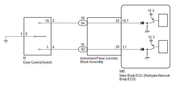
The main body ECU (multiplex network body ECU) receives switch signals from the power window regulator switch assembly on the front passenger door and activates the door lock motor on each door according to these signals.
WIRING DIAGRAM
CAUTION / NOTICE / HINT
NOTICE:
Before replacing the main body ECU (multiplex network body ECU), refer to Registration*.
Click here
.gif)
- *: w/ Smart Key System
PROCEDURE
|
1. |
READ VALUE USING TECHSTREAM (Door Lock SW-Lock, Door Lock SW-Unlock) |
(a) Connect the Techstream to the DLC3.
(b) Turn the ignition switch to ON.
(c) Turn the Techstream on.
(d) Enter the following menus: Body Electrical / Main Body / Data List.
(e) Read the Data List according to the display on the Techstream.
Body Electrical > Main Body > Data List|
Tester Display |
Measurement Item |
Range |
Normal Condition |
Diagnostic Note |
|---|---|---|---|---|
|
Door Lock SW-Lock |
Door control switch assembly lock signal |
OFF or ON |
OFF: Lock side of door control switch assembly not pushed ON: Lock side of door control switch assembly pushed |
- |
|
Door Lock SW-Unlock |
Door control switch assembly unlock signal |
OFF or ON |
OFF: Unlock side of door control switch assembly not pushed ON: Unlock side of door control switch assembly pushed |
- |
|
Tester Display |
|---|
|
Door Lock SW-Lock |
|
Door Lock SW-Unlock |
OK:
The Techstream indicates ON or OFF according to the switch operation shown in the table.
| OK | .gif) |
REPLACE MAIN BODY ECU (MULTIPLEX NETWORK BODY ECU)
|
|
.gif)
|
2. |
INSPECT DOOR CONTROL SWITCH ASSEMBLY |
(a) Remove the door control switch assembly.
Click here
(b) Inspect the door control switch assembly.
Click here
| NG | |
REPLACE DOOR CONTROL SWITCH ASSEMBLY
|
|
|
3. |
CHECK HARNESS AND CONNECTOR (DOOR CONTROL SWITCH ASSEMBLY - INSTRUMENT PANEL JUNCTION BLOCK ASSEMBLY) |
(a) Disconnect the 3A and 3D instrument panel junction block assembly connectors.
(b) Measure the resistance according to the value(s) in the table below.
Standard Resistance:
|
Tester Connection |
Condition |
Specified Condition |
|---|---|---|
|
I9-2 (UL) - 3A-39 |
Always |
Below 1 Ω |
|
I9-4 (L) - 3D-16 |
Always |
Below 1 Ω |
|
I9-5 (E) - Body ground |
Always |
Below 1 Ω |
|
I9-2 (UL) or 3A-39 - Body ground |
Always |
10 kΩ or higher |
|
I9-4 (L) or 3D-16 - Body ground |
Always |
10 kΩ or higher |
| NG | |
REPAIR OR REPLACE HARNESS OR CONNECTOR |
|
|
4. |
INSPECT INSTRUMENT PANEL JUNCTION BLOCK ASSEMBLY |
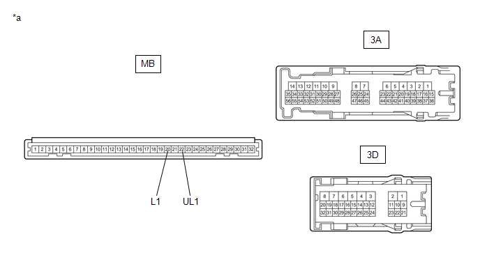
(a) Remove the instrument panel junction block assembly.
Click here
(b) Remove the main body ECU (multiplex network body ECU).
|
*a |
Component without harness connected (Instrument Panel Junction Block Assembly) |
- |
- |
(c) Measure the resistance according to the value(s) in the table below.
Standard Resistance:
|
Tester Connection |
Condition |
Specified Condition |
|---|---|---|
|
MB-22 (UL1) - 3A-39 |
Always |
Below 1 Ω |
|
MB-20 (L1) - 3D-16 |
Always |
Below 1 Ω |
| OK | |
REPLACE MAIN BODY ECU (MULTIPLEX NETWORK BODY ECU)
|
| NG | |
REPLACE INSTRUMENT PANEL JUNCTION BLOCK ASSEMBLY
|
 All Doors LOCK/UNLOCK Functions do not Operate Via Door Control Switch or Door
Key Cylinder
All Doors LOCK/UNLOCK Functions do not Operate Via Door Control Switch or Door
Key Cylinder
DESCRIPTION
The main body ECU (multiplex network body ECU) receives switch signals from the
multiplex network master switch assembly and driver door key cylinder lock or unlock
switch signals fro ...
 Improper Operation
DESCRIPTION
In cases where doors locked (lock) by themselves even though a door lock operation
was not performed, possible causes include vehicle-side malfunction, environmental
malfunction, or o ...
Other materials:
Toyota CH-R Service Manual > Steering Gear: Reassembly
REASSEMBLY
PROCEDURE
1. INSTALL NO. 2 STEERING RACK BOOT
(a) Apply lithium soap base glycol grease to the inside of the small
opening of a new No. 2 steering rack boot.
(b) Install the No. 2 steering rack boot to the groove on the ra ...
Toyota CH-R Service Manual > Can Communication System: Utility
UTILITY
INITIALIZE THE CONNECTION INFORMATION OF A GATEWAY FUNCTION EQUIPPED ECU (BUS
MONITOR ECU)
(a) Connect the Techstream to the DLC3.
(b) Turn the ignition switch to ON.
(c) Turn the Techstream on.
(d) Enter the following menus:
for Body Electrical / Central Gateway / Utility / I ...
Toyota C-HR (AX20) 2023-2025 Owner's Manual
Toyota CH-R Owners Manual
- For safety and security
- Instrument cluster
- Operation of each component
- Driving
- Interior features
- Maintenance and care
- When trouble arises
- Vehicle specifications
- For owners
Toyota CH-R Service Manual
- Introduction
- Maintenance
- Audio / Video
- Cellular Communication
- Navigation / Multi Info Display
- Park Assist / Monitoring
- Brake (front)
- Brake (rear)
- Brake Control / Dynamic Control Systems
- Brake System (other)
- Parking Brake
- Axle And Differential
- Drive Shaft / Propeller Shaft
- K114 Cvt
- 3zr-fae Battery / Charging
- Networking
- Power Distribution
- Power Assist Systems
- Steering Column
- Steering Gear / Linkage
- Alignment / Handling Diagnosis
- Front Suspension
- Rear Suspension
- Tire / Wheel
- Tire Pressure Monitoring
- Door / Hatch
- Exterior Panels / Trim
- Horn
- Lighting (ext)
- Mirror (ext)
- Window / Glass
- Wiper / Washer
- Door Lock
- Heating / Air Conditioning
- Interior Panels / Trim
- Lighting (int)
- Meter / Gauge / Display
- Mirror (int)
- Power Outlets (int)
- Pre-collision
- Seat
- Seat Belt
- Supplemental Restraint Systems
- Theft Deterrent / Keyless Entry

0.011