Toyota CH-R Service Manual: Radio Receiver Power Source Circuit
DESCRIPTION
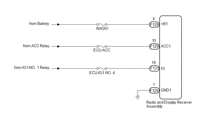
This is the power source circuit to operate the radio and display receiver assembly.
WIRING DIAGRAM
CAUTION / NOTICE / HINT
NOTICE:
Inspect the fuses for circuits related to this system before performing the following procedure.
PROCEDURE
|
1. |
CHECK HARNESS AND CONNECTOR (RADIO AND DISPLAY RECEIVER ASSEMBLY - POWER SOURCE) |
(a) Disconnect the F129 and F131 radio and display receiver assembly connectors.
(b) Measure the resistance according to the value(s) in the table below.
Standard Resistance:
|
Tester Connection |
Condition |
Specified Condition |
|---|---|---|
|
F129-1 (GND1) - Body ground |
Always |
Below 1 Ω |
(c) Measure the voltage according to the value(s) in the table below.
Standard Voltage:
|
Tester Connection |
Switch Condition |
Specified Condition |
|---|---|---|
|
F129-4 (+B1) - F129-1 (GND1) |
Always |
11 to 14 V |
|
F129-15 (ACC1) - F129-1 (GND1) |
Engine switch on (ACC) |
11 to 14 V |
|
F131-19 (IG) - F129-1 (GND1) |
Engine switch on (IG) |
11 to 14 V |
| OK | .gif) |
PROCEED TO NEXT SUSPECTED AREA SHOWN IN PROBLEM SYMPTOMS TABLE |
| NG | |
REPAIR OR REPLACE HARNESS OR CONNECTOR |
 Microphone Circuit
DESCRIPTION
The radio and display receiver assembly, map light assembly and telephone microphone
assembly are connected to each other using the microphone connection detection signal
lines.
Usin ...

Other materials:
Toyota CH-R Service Manual > Airbag System: Diagnosis System
DIAGNOSIS SYSTEM
CHECK DLC3
(a) Check the DLC3.
Click here
FUNCTION OF SRS WARNING LIGHT
(a) Primary check
(1) Turn the ignition switch off. Wait for at least 2 seconds, then turn the
ignition switch ON. The SRS warning light comes on for approximately 6 seconds and
diagnosis of the airb ...
Toyota CH-R Service Manual > Front Disc Brake Pad: Removal
REMOVAL
CAUTION / NOTICE / HINT
NOTICE:
Immediately after installing the brake pads, the braking performance
may be reduced. Always perform a road test in a safe place while paying
attention to the surroundings.
Immediately after installing the front disc brake pads, the brake ...
Toyota C-HR (AX20) 2023-2026 Owner's Manual
Toyota CH-R Owners Manual
- For safety and security
- Instrument cluster
- Operation of each component
- Driving
- Interior features
- Maintenance and care
- When trouble arises
- Vehicle specifications
- For owners
Toyota CH-R Service Manual
- Introduction
- Maintenance
- Audio / Video
- Cellular Communication
- Navigation / Multi Info Display
- Park Assist / Monitoring
- Brake (front)
- Brake (rear)
- Brake Control / Dynamic Control Systems
- Brake System (other)
- Parking Brake
- Axle And Differential
- Drive Shaft / Propeller Shaft
- K114 Cvt
- 3zr-fae Battery / Charging
- Networking
- Power Distribution
- Power Assist Systems
- Steering Column
- Steering Gear / Linkage
- Alignment / Handling Diagnosis
- Front Suspension
- Rear Suspension
- Tire / Wheel
- Tire Pressure Monitoring
- Door / Hatch
- Exterior Panels / Trim
- Horn
- Lighting (ext)
- Mirror (ext)
- Window / Glass
- Wiper / Washer
- Door Lock
- Heating / Air Conditioning
- Interior Panels / Trim
- Lighting (int)
- Meter / Gauge / Display
- Mirror (int)
- Power Outlets (int)
- Pre-collision
- Seat
- Seat Belt
- Supplemental Restraint Systems
- Theft Deterrent / Keyless Entry

0.0081