Toyota CH-R Service Manual: Door Control Receiver
Components
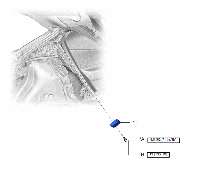
COMPONENTS
ILLUSTRATION
|
*A |
for Type A |
*B |
for Type B |
|
*1 |
DOOR CONTROL AND TIRE PRESSURE MONITORING SYSTEM RECEIVER ASSEMBLY |
- |
- |
.png) |
N*m (kgf*cm, ft.*lbf): Specified torque |
- |
- |
Removal
REMOVAL
PROCEDURE
1. REMOVE ROOF SIDE INNER GARNISH ASSEMBLY LH
Click here
.gif)
2. REMOVE DOOR CONTROL AND TIRE PRESSURE MONITORING SYSTEM RECEIVER ASSEMBLY
NOTICE:
- Do not drop, strike or otherwise subject the door control and tire pressure monitoring system receiver assembly to impact.
- If the door control and tire pressure monitoring system receiver assembly is subjected to an impact, replace it with a new one.
|
(a) Remove the bolt. |
|
.png)
(b) Disengage the guides.
(c) Disconnect the connector to remove the door control and tire pressure monitoring system receiver assembly.
Installation
INSTALLATION
PROCEDURE
1. INSTALL DOOR CONTROL AND TIRE PRESSURE MONITORING SYSTEM RECEIVER ASSEMBLY
NOTICE:
- Do not drop, strike or otherwise subject the door control and tire pressure monitoring system receiver assembly to impact.
- If the door control and tire pressure monitoring system receiver assembly is subjected to an impact, replace it with a new one.
|
(a) Connect the connector. |
|
.png)
(b) Engage the guides.
(c) Install the door control and tire pressure monitoring system receiver assembly with the bolt.
Torque:
for Type A :
8.0 N·m {82 kgf·cm, 71 in·lbf}
for Type B :
13 N·m {133 kgf·cm, 10 ft·lbf}
2. INSTALL ROOF SIDE INNER GARNISH ASSEMBLY LH
Click here
.gif)
 Installation
INSTALLATION
PROCEDURE
1. INSTALL BACK DOOR LOCK ASSEMBLY
HINT:
Make sure to remove the string before installing a new back door lock assembly.
(a) Apply MP grease to the sliding parts of the bac ...
 Door Control Relay
Components
COMPONENTS
ILLUSTRATION
*1
DOUBLE LOCK DOOR CONTROL RELAY ASSEMBLY
-
-
N*m (kgf*cm, ft.*lbf): Specified torque
...
Other materials:
Toyota CH-R Service Manual > Vehicle Stability Control System: Open in Stop Light Switch Circuit (C1249)
DESCRIPTION
The skid control ECU (brake actuator assembly) receives stop light switch signals
and uses them to determine whether or not the brakes are applied. DTCs may be stored
if either of the following occurs:
Stop light switch stuck on malfunction.
The accelerator and brake ped ...
Toyota CH-R Service Manual > Front Lower Suspension Arm: Installation
INSTALLATION
PROCEDURE
1. INSTALL FRONT LOWER NO. 1 SUSPENSION ARM SUB-ASSEMBLY
(a) Temporarily install the front lower No. 1 suspension arm sub-assembly LH
to the front suspension crossmember sub-assembly with the 2 bolts and nut.
(b) Install the front lower No. 1 suspension arm sub-assembly ...
Toyota C-HR (AX20) 2023-2026 Owner's Manual
Toyota CH-R Owners Manual
- For safety and security
- Instrument cluster
- Operation of each component
- Driving
- Interior features
- Maintenance and care
- When trouble arises
- Vehicle specifications
- For owners
Toyota CH-R Service Manual
- Introduction
- Maintenance
- Audio / Video
- Cellular Communication
- Navigation / Multi Info Display
- Park Assist / Monitoring
- Brake (front)
- Brake (rear)
- Brake Control / Dynamic Control Systems
- Brake System (other)
- Parking Brake
- Axle And Differential
- Drive Shaft / Propeller Shaft
- K114 Cvt
- 3zr-fae Battery / Charging
- Networking
- Power Distribution
- Power Assist Systems
- Steering Column
- Steering Gear / Linkage
- Alignment / Handling Diagnosis
- Front Suspension
- Rear Suspension
- Tire / Wheel
- Tire Pressure Monitoring
- Door / Hatch
- Exterior Panels / Trim
- Horn
- Lighting (ext)
- Mirror (ext)
- Window / Glass
- Wiper / Washer
- Door Lock
- Heating / Air Conditioning
- Interior Panels / Trim
- Lighting (int)
- Meter / Gauge / Display
- Mirror (int)
- Power Outlets (int)
- Pre-collision
- Seat
- Seat Belt
- Supplemental Restraint Systems
- Theft Deterrent / Keyless Entry

0.0065