Toyota CH-R Service Manual: Terminals Of Ecu
TERMINALS OF ECU
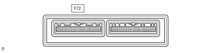
CHECK AIR CONDITIONING AMPLIFIER ASSEMBLY (for TMMT Made)
(a) Disconnect the F72 air conditioning amplifier assembly connector.
(b) Measure the voltage and resistance according to the value(s) in the table below.
HINT:
Measure the values on the wire harness side with the connector disconnected.
|
Tester Connection |
Wiring Color |
Terminal Description |
Switch Condition |
Specified Condition |
|---|---|---|---|---|
|
F72-5 (IG+) - F72-29 (GND) |
B - W-B |
Power source (IG) |
Ignition switch ON |
11 to 14 V |
|
Ignition switch off |
Below 1 V |
|||
|
F72-1 (B) - F72-29 (GND) |
V - W-B |
Battery power supply |
Always |
11 to 14 V |
|
F72-29 (GND) - Body ground |
W-B - Body ground |
Ground |
Always |
Below 1 Ω |
If the result is not as specified, there may be a malfunction in the wire harness.
(c) Reconnect the F72 air conditioning amplifier assembly connector.
(d) Measure the voltage and check for pulses according to the value(s) in the table below.
|
Tester Connection |
Wiring Color |
Terminal Description |
Switch Condition |
Specified Condition |
|---|---|---|---|---|
|
F72-26 (RDFG) - F72-29 (GND) |
P - W-B |
Rear window defogger signal |
Ignition switch ON, rear window defogger switch off |
11 to 14 V |
|
Ignition switch ON, rear window defogger switch on |
Below 1 V |
|||
|
F72-3 (LIN1) - F72-29 (GND) |
L - W-B |
LIN communication line |
Ignition switch ON |
Pulse generation |
If the result is not as specified, the air conditioning amplifier assembly may be malfunctioning.
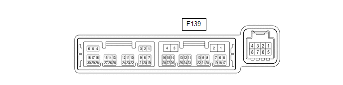
CHECK AIR CONDITIONING AMPLIFIER ASSEMBLY (for TMC Made)
(a) Disconnect the F139 air conditioning amplifier assembly connector.
(b) Measure the voltage and resistance according to the value(s) in the table below.
HINT:
Measure the values on the wire harness side with the connector disconnected.
|
Tester Connection |
Wiring Color |
Terminal Description |
Switch Condition |
Specified Condition |
|---|---|---|---|---|
|
F139-2 (IG+) - F139-4 (GND) |
B - W-B |
Power source (IG) |
Ignition switch ON |
11 to 14 V |
|
Ignition switch off |
Below 1 V |
|||
|
F139-1 (B) - F139-4 (GND) |
V - W-B |
Battery power supply |
Always |
11 to 14 V |
|
F139-4 (GND) - Body ground |
W-B - Body ground |
Ground |
Always |
Below 1 Ω |
If the result is not as specified, there may be a malfunction in the wire harness.
(c) Reconnect the F139 air conditioning amplifier assembly connector.
(d) Measure the voltage and check for pulses according to the value(s) in the table below.
|
Tester Connection |
Wiring Color |
Terminal Description |
Switch Condition |
Specified Condition |
|---|---|---|---|---|
|
F139-5 (RDFG) - F139-4 (GND) |
P - W-B |
Rear window defogger signal |
Ignition switch ON, rear window defogger switch off |
11 to 14 V |
|
Ignition switch ON, rear window defogger switch on |
Below 1 V |
|||
|
F139-14 (LIN1) - F139-4 (GND) |
BE - W-B |
LIN communication line |
Ignition switch ON |
Pulse generation |
If the result is not as specified, the air conditioning amplifier assembly may be malfunctioning.
CHECK AIR CONDITIONING CONTROL ASSEMBLY
(a) Check for pulses according to the value(s) in the table below.

|
Tester Connection |
Wiring Color |
Terminal Description |
Switch Condition |
Specified Condition |
|---|---|---|---|---|
|
F61-2 (LIN1) - F61-16 (GND) |
L - W-B*1 BE - W-B*2 |
LIN communication line |
Ignition switch ON |
Pulse generation |
- *1: for TMMT Made
- *2: for TMC Made
If the result is not as specified, the air conditioning control assembly may be malfunctioning.
 Problem Symptoms Table
PROBLEM SYMPTOMS TABLE
HINT:
Inspect the fuses and relays related to this system before inspecting
the suspected areas below.
Use the table below to help determine the cause of probl ...
 Diagnosis System
DIAGNOSIS SYSTEM
CHECK DLC3
(a) Check the DLC3.
Click here
INSPECT BATTERY VOLTAGE
(a) Measure the battery voltage.
Standard voltage:
11 to 14 V
If the voltage is below 11 V, recharge or ...
Other materials:
Toyota CH-R Service Manual > Rear Brake(for Tmmt Made): Reassembly
REASSEMBLY
PROCEDURE
1. TEMPORARILY TIGHTEN REAR DISC BRAKE BLEEDER PLUG
(a) Temporarily install the rear disc brake bleeder plug to the rear disc brake
cylinder assembly.
HINT:
Fully tighten the rear disc brake bleeder plug after bleeding the system.
2. INSTALL REAR DISC BRAKE BLEEDER PLUG ...
Toyota CH-R Service Manual > Revolution Sensor: Components
COMPONENTS
ILLUSTRATION
*1
AIR CLEANER CAP WITH AIR CLEANER HOSE
*2
AIR CLEANER CASE SUB-ASSEMBLY
*3
BATTERY CLAMP SUB-ASSEMBLY
*4
ECM
*5
NO. 1 AIR CLEANER INLET
* ...
Toyota C-HR (AX20) 2023-2026 Owner's Manual
Toyota CH-R Owners Manual
- For safety and security
- Instrument cluster
- Operation of each component
- Driving
- Interior features
- Maintenance and care
- When trouble arises
- Vehicle specifications
- For owners
Toyota CH-R Service Manual
- Introduction
- Maintenance
- Audio / Video
- Cellular Communication
- Navigation / Multi Info Display
- Park Assist / Monitoring
- Brake (front)
- Brake (rear)
- Brake Control / Dynamic Control Systems
- Brake System (other)
- Parking Brake
- Axle And Differential
- Drive Shaft / Propeller Shaft
- K114 Cvt
- 3zr-fae Battery / Charging
- Networking
- Power Distribution
- Power Assist Systems
- Steering Column
- Steering Gear / Linkage
- Alignment / Handling Diagnosis
- Front Suspension
- Rear Suspension
- Tire / Wheel
- Tire Pressure Monitoring
- Door / Hatch
- Exterior Panels / Trim
- Horn
- Lighting (ext)
- Mirror (ext)
- Window / Glass
- Wiper / Washer
- Door Lock
- Heating / Air Conditioning
- Interior Panels / Trim
- Lighting (int)
- Meter / Gauge / Display
- Mirror (int)
- Power Outlets (int)
- Pre-collision
- Seat
- Seat Belt
- Supplemental Restraint Systems
- Theft Deterrent / Keyless Entry

0.0081