Toyota CH-R Service Manual: Rear Power Window Switch
Components
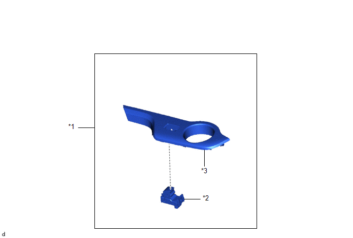
COMPONENTS
ILLUSTRATION
|
*1 |
POWER WINDOW REGULATOR SWITCH ASSEMBLY WITH REAR DOOR UPPER ARMREST BASE PANEL |
*2 |
REAR POWER WINDOW REGULATOR SWITCH ASSEMBLY |
|
*3 |
REAR DOOR UPPER ARMREST BASE PANEL |
- |
- |
Removal
REMOVAL
CAUTION / NOTICE / HINT
HINT:
- Use the same procedure for the RH and LH sides.
- The procedure listed below is for the LH side.
PROCEDURE
1. REMOVE REAR POWER WINDOW REGULATOR SWITCH ASSEMBLY WITH REAR DOOR ARMREST BASE UPPER PANEL
Click here
.gif)
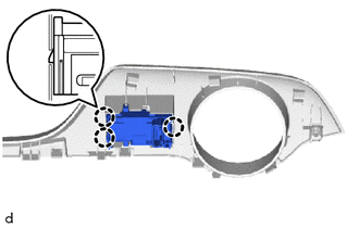
2. REMOVE REAR POWER WINDOW REGULATOR SWITCH ASSEMBLY
|
(a) Disengage the claws to remove the rear power window regulator switch assembly. |
|
Inspection
INSPECTION
PROCEDURE
1. INSPECT REAR POWER WINDOW REGULATOR SWITCH ASSEMBLY
|
(a) Check the resistance. (1) Measure the resistance according to the value(s) in the table below. Standard Resistance:
If the result is not as specified, replace the rear power window regulator switch assembly. |
|
.png)
(b) Check that the LED illuminates.
(1) Apply battery voltage to the power window regulator switch assembly and check that the LED illuminates.
OK:
|
Battery Connection |
Specified Condition |
|---|---|
|
Battery positive (+) → 3 (ILL+) Battery negative (-) → 1 (ILL-) |
LED illuminates |
If the result is not as specified, replace the rear power window regulator switch assembly.
Installation
INSTALLATION
CAUTION / NOTICE / HINT
HINT:
- Use the same procedure for the RH and LH sides.
- The procedure listed below is for the LH side.
PROCEDURE
1. INSTALL REAR POWER WINDOW REGULATOR SWITCH ASSEMBLY
|
(a) Engage the claws to install the rear power window regulator switch assembly. |
|
.png)
2. INSTALL REAR POWER WINDOW REGULATOR SWITCH ASSEMBLY WITH REAR DOOR ARMREST BASE UPPER PANEL
Click here
.gif)
 Installation
INSTALLATION
CAUTION / NOTICE / HINT
HINT:
Use the same procedure for the RH and LH sides.
The procedure listed below is for the LH side.
PROCEDURE
1. INSTALL POWER WINDOW REGUL ...
 Relay
Relay
On-vehicle Inspection
ON-VEHICLE INSPECTION
PROCEDURE
1. INSPECT DEFOGGER RELAY
(a) Check the resistance.
(1) Measure the resistance according to the value(s) in the table below.
...
Other materials:
Toyota CH-R Service Manual > Vehicle Stability Control System: TRAC does not Operate
DESCRIPTION
When ABS, TRAC or VSC is operating, the skid control ECU (brake actuator assembly)
blinks the slip indicator light to inform the driver that slippage occurred.
When in VSC off mode, or TRAC and VSC are disabled, the multi-information display
in the combination meter assembly displa ...
Toyota CH-R Service Manual > Brake Actuator: Removal
REMOVAL
CAUTION / NOTICE / HINT
The necessary procedures (adjustment, calibration, initialization, or registration)
that must be performed after parts are removed, installed, or replaced during the
brake actuator assembly removal/installation are shown below.
Necessary Procedure After Parts R ...
Toyota C-HR (AX20) 2023-2026 Owner's Manual
Toyota CH-R Owners Manual
- For safety and security
- Instrument cluster
- Operation of each component
- Driving
- Interior features
- Maintenance and care
- When trouble arises
- Vehicle specifications
- For owners
Toyota CH-R Service Manual
- Introduction
- Maintenance
- Audio / Video
- Cellular Communication
- Navigation / Multi Info Display
- Park Assist / Monitoring
- Brake (front)
- Brake (rear)
- Brake Control / Dynamic Control Systems
- Brake System (other)
- Parking Brake
- Axle And Differential
- Drive Shaft / Propeller Shaft
- K114 Cvt
- 3zr-fae Battery / Charging
- Networking
- Power Distribution
- Power Assist Systems
- Steering Column
- Steering Gear / Linkage
- Alignment / Handling Diagnosis
- Front Suspension
- Rear Suspension
- Tire / Wheel
- Tire Pressure Monitoring
- Door / Hatch
- Exterior Panels / Trim
- Horn
- Lighting (ext)
- Mirror (ext)
- Window / Glass
- Wiper / Washer
- Door Lock
- Heating / Air Conditioning
- Interior Panels / Trim
- Lighting (int)
- Meter / Gauge / Display
- Mirror (int)
- Power Outlets (int)
- Pre-collision
- Seat
- Seat Belt
- Supplemental Restraint Systems
- Theft Deterrent / Keyless Entry

0.0079