Toyota CH-R Service Manual: Driver Side Power Window Auto Up / Down Function does not Operate with Power Window Master Switch
DESCRIPTION
If the manual up and down functions operate normally but the auto up and down functions do not, the power window control system may be in fail-safe mode.
If power window initialization has not been performed, the auto up and down functions will not operate.
Click here
.gif)
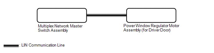
WIRING DIAGRAM
CAUTION / NOTICE / HINT
NOTICE:
- The power window control system uses the LIN communication system. Inspect
the communication function by following How to Proceed with Troubleshooting.
Troubleshoot the power window control system after confirming that the communication
system is functioning properly.
Click here
- If the power window regulator motor assembly (for driver door) has been
replaced with a new one, initialize the power window control system.
Click here
- Check that power window system customize setting "D Window Auto Up"
and "D Window Auto Down" are set to "ON" before performing the following
procedure.
Click here
- After the catch protection function has operated, the auto up function will not operate the first time the power window auto up switch is operated. The auto up function will operate normally after the first power window switch operation.
HINT:
If the pulse sensor built into the power window regulator motor assembly (for driver door) is malfunctioning, the power window control system will enter fail-safe mode. The remote up and down and auto up and down functions cannot be operated during fail-safe mode. However, the power window can be closed by holding the multiplex network master switch assembly at the auto up position, and opened manually by pushing down the multiplex network master switch assembly.
Click here
PROCEDURE
|
1. |
READ VALUE USING TECHSTREAM (MASTER SWITCH) |
(a) Connect the Techstream to the DLC3.
(b) Turn the ignition switch to ON.
(c) Turn the Techstream on.
(d) Enter the following menus: Body Electrical / Master switch / Data List.
(e) Read the Data List according to the display on the Techstream.
Body Electrical > Master Switch > Data List|
Tester Display |
Measurement Item |
Range |
Normal Condition |
Diagnostic Note |
|---|---|---|---|---|
|
D Door P/W Auto SW |
Driver door power window auto switch signal |
OFF or ON |
OFF: Driver door power window auto up or auto down switch not being operated ON: Driver door power window auto up or auto down switch being operated |
- |
|
Tester Display |
|---|
|
D Door P/W Auto SW |
OK:
On the Techstream screen, ON or OFF is displayed accordingly.
| NG | .gif) |
REPLACE MULTIPLEX NETWORK MASTER SWITCH ASSEMBLY |
|
.gif)
|
2. |
READ VALUE USING TECHSTREAM (D-DOOR MOTOR) |
(a) Enter the following menus: Body Electrical / D-Door Motor / Data List.
(b) Read the Data List according to the display on the Techstream.
Body Electrical > D-Door Motor > Data List|
Tester Display |
Measurement Item |
Range |
Normal Condition |
Diagnostic Note |
|---|---|---|---|---|
|
D Door P/W Auto SW |
Driver door power window auto switch signal |
OFF or ON |
OFF: Driver door power window auto up or auto down switch not being operated ON: Driver door power window auto up or auto down switch being operated |
- |
|
Tester Display |
|---|
|
D Door P/W Auto SW |
OK:
On the Techstream screen, ON or OFF is displayed accordingly.
| NG | |
GO TO STEP 5 |
|
|
3. |
PERFORM INITIALIZATION (FOR DRIVER DOOR) |
(a) Initialize the power window regulator motor assembly (for driver door).
Click here
|
|
4. |
CHECK POWER WINDOW CONTROL SYSTEM (AUTO UP / DOWN FUNCTION) |
(a) Check that the driver door power window moves when the auto up and down functions of the multiplex network master switch assembly are operated.
Click here
OK:
Driver door auto up and down functions are normal.
| OK | |
END (PROBLEM DUE TO INITIALIZATION FAILURE) |
| NG | |
REPLACE POWER WINDOW REGULATOR MOTOR ASSEMBLY (FOR DRIVER DOOR) |
|
5. |
REPLACE MULTIPLEX NETWORK MASTER SWITCH ASSEMBLY |
(a) Replace the multiplex network master switch assembly.
Click here
|
|
6. |
CHECK POWER WINDOW CONTROL SYSTEM (AUTO UP / DOWN FUNCTION) |
(a) Check that the driver door power window moves when the auto up and down functions of the multiplex network master switch assembly are operated.
Click here
OK:
Driver door auto up and down functions are normal.
| OK | |
END (MULTIPLEX NETWORK MASTER SWITCH ASSEMBLY WAS DEFECTIVE) |
| NG | |
REPLACE POWER WINDOW REGULATOR MOTOR ASSEMBLY (FOR DRIVER DOOR) |
 Rear Power Window RH does not Operate with Rear Power Window Switch RH
DESCRIPTION
When the ignition switch is ON, the power window regulator motor assembly (for
rear RH door) is operated by the rear power window regulator switch assembly (for
RH door). The power wi ...
 Front Passenger Side Power Window Auto Up / Down Function does not Operate with
Front Passenger Side Power Window Switch
Front Passenger Side Power Window Auto Up / Down Function does not Operate with
Front Passenger Side Power Window Switch
DESCRIPTION
If the manual up and down functions operate normally but the auto up and down
functions do not, the power window control system may be in fail-safe mode.
If power window initialization ...
Other materials:
Toyota CH-R Service Manual > Toyota Entune System: DCM Data Signal Circuit between Navigation ECU and DCM
DESCRIPTION
This circuit is used to send and receive signals between the DCM (Telematics
Transceiver) and radio and display receiver assembly.
WIRING DIAGRAM
PROCEDURE
1.
CHECK VEHICLE TYPE
(a) Check vehicle type.
Result
Proceed to
...
Toyota CH-R Service Manual > Rear Combination Light Assembly(for Led Type): Removal
REMOVAL
CAUTION / NOTICE / HINT
HINT:
Use the same procedure for the RH side and LH side.
The following procedure is for the LH side.
PROCEDURE
1. REMOVE REAR COMBINATION LIGHT COVER
(a) Disengage the claws to remove the rear combination light cover as shown in
the illustra ...
Toyota C-HR (AX20) 2023-2025 Owner's Manual
Toyota CH-R Owners Manual
- For safety and security
- Instrument cluster
- Operation of each component
- Driving
- Interior features
- Maintenance and care
- When trouble arises
- Vehicle specifications
- For owners
Toyota CH-R Service Manual
- Introduction
- Maintenance
- Audio / Video
- Cellular Communication
- Navigation / Multi Info Display
- Park Assist / Monitoring
- Brake (front)
- Brake (rear)
- Brake Control / Dynamic Control Systems
- Brake System (other)
- Parking Brake
- Axle And Differential
- Drive Shaft / Propeller Shaft
- K114 Cvt
- 3zr-fae Battery / Charging
- Networking
- Power Distribution
- Power Assist Systems
- Steering Column
- Steering Gear / Linkage
- Alignment / Handling Diagnosis
- Front Suspension
- Rear Suspension
- Tire / Wheel
- Tire Pressure Monitoring
- Door / Hatch
- Exterior Panels / Trim
- Horn
- Lighting (ext)
- Mirror (ext)
- Window / Glass
- Wiper / Washer
- Door Lock
- Heating / Air Conditioning
- Interior Panels / Trim
- Lighting (int)
- Meter / Gauge / Display
- Mirror (int)
- Power Outlets (int)
- Pre-collision
- Seat
- Seat Belt
- Supplemental Restraint Systems
- Theft Deterrent / Keyless Entry

0.0185