Toyota CH-R Service Manual: Removal
REMOVAL
PROCEDURE
1. REMOVE REAR SPOILER
Click here
.gif)
2. REMOVE REAR WIPER MOTOR ASSEMBLY
Click here
3. REMOVE REAR LIGHT ASSEMBLY (for Bulb Type)
Click here
4. REMOVE REAR LIGHT ASSEMBLY (for LED Type)
Click here
5. DISCONNECT NO. 1 BACK DOOR WIRE
|
(a) Disconnect the 2 connectors from the back door glass. |
|
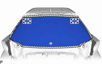
6. REMOVE BACK DOOR GLASS
(a) Apply protective tape to the area around the installation position of the back door glass on the back door panel to prevent it from being scratched.
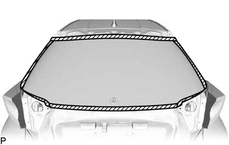
.png) |
Protective Tape |
|
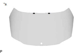
(b) Place matchmarks on the back door glass and back door panel at the locations indicated in the illustration. HINT: Matchmarks are not necessary if the back door glass is not going to be reused. |
|
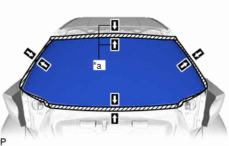
|
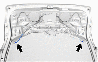
(c) Pass a piano wire between the back door panel and back door glass from the interior. |
|
(d) Tie both wire ends to wooden blocks or similar objects that can serve as handles.
(e) Cut the adhesive by pulling the piano wire around the back door glass.
NOTICE:
- When separating the back door glass, take care not to damage the paint or interior and exterior ornaments.
- When cutting the adhesive, take care not to damage the connectors on the back door glass.
- Do not pull the piano wire in a vertical direction, but pull it in a horizontal direction.
|
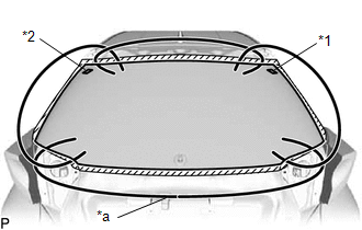
(f) Using suction cups, disengage the No. 1 back window glass spacer and No. 2 back window glass spacer and remove the back door glass. NOTICE:
|
|
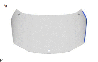
7. REMOVE BACK WINDOW OUTSIDE MOULDING LH
(a) When reusing the back door glass:
|
(1) Using a scraper, remove the back window outside moulding LH. NOTICE:
|
|
8. REMOVE BACK WINDOW OUTSIDE MOULDING RH
HINT:
Use the same procedure as for the LH side.
9. REMOVE NO. 2 BACK WINDOW GLASS SPACER
(a) When reusing the back door glass:
|
(1) Using a scraper, remove the No. 2 back window glass spacer. NOTICE:
|
|
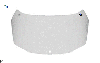
10. REMOVE NO. 1 BACK WINDOW GLASS SPACER
HINT:
Use the same procedure as for the No. 2 back window glass spacer.
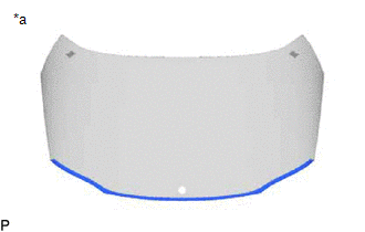
11. REMOVE BACK WINDOW LOWER MOULDING
(a) When reusing the back door glass:
|
(1) Using a scraper, remove the back window lower moulding. NOTICE:
|
|
12. REMOVE BACK DOOR GLASS SPACER (for Upper Side)
(a) When reusing the back door glass:
|
(1) Using a scraper, remove the 2 back door glass spacers. NOTICE:
|
|
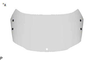
13. REMOVE BACK DOOR GLASS SPACER (for Side)
|
(a) When reusing the back door glass: (1) Using a scraper, remove the 4 back door glass spacers. NOTICE:
|
|
 Components
COMPONENTS
ILLUSTRATION
*A
for Upper Side
*B
for Side
*1
BACK DOOR GLASS
*2
BACK DOOR GLASS SPACER
...
 Installation
INSTALLATION
PROCEDURE
1. CLEAN BACK DOOR GLASS
(a) When reusing the back door glass:
(1) Using a scraper, remove any remaining adhesive residue from the back
window glass.
NOT ...
Other materials:
Toyota CH-R Service Manual > K114 Cvt: Shift Lever Knob
Components
COMPONENTS
ILLUSTRATION
*1
SHIFT LEVER CAP
*2
SHIFT LEVER KNOB SUB-ASSEMBLY
Removal
REMOVAL
PROCEDURE
1. REMOVE SHIFT LEVER CAP
Click here
2. REMOVE SHIFT LEVER KNOB SUB-ASSEMBLY
Remove in this ...
Toyota CH-R Service Manual > Front Drive Shaft Assembly: Disassembly
DISASSEMBLY
PROCEDURE
1. SEPARATE FRONT NO. 2 AXLE INBOARD JOINT BOOT CLAMP
(a) Secure the drive shaft in a vise between aluminum plates.
NOTICE:
Do not overtighten the vise.
(b) Using pliers, separate the front No. 2 axle inboard joint boot clamp.
...
Toyota C-HR (AX20) 2023-2026 Owner's Manual
Toyota CH-R Owners Manual
- For safety and security
- Instrument cluster
- Operation of each component
- Driving
- Interior features
- Maintenance and care
- When trouble arises
- Vehicle specifications
- For owners
Toyota CH-R Service Manual
- Introduction
- Maintenance
- Audio / Video
- Cellular Communication
- Navigation / Multi Info Display
- Park Assist / Monitoring
- Brake (front)
- Brake (rear)
- Brake Control / Dynamic Control Systems
- Brake System (other)
- Parking Brake
- Axle And Differential
- Drive Shaft / Propeller Shaft
- K114 Cvt
- 3zr-fae Battery / Charging
- Networking
- Power Distribution
- Power Assist Systems
- Steering Column
- Steering Gear / Linkage
- Alignment / Handling Diagnosis
- Front Suspension
- Rear Suspension
- Tire / Wheel
- Tire Pressure Monitoring
- Door / Hatch
- Exterior Panels / Trim
- Horn
- Lighting (ext)
- Mirror (ext)
- Window / Glass
- Wiper / Washer
- Door Lock
- Heating / Air Conditioning
- Interior Panels / Trim
- Lighting (int)
- Meter / Gauge / Display
- Mirror (int)
- Power Outlets (int)
- Pre-collision
- Seat
- Seat Belt
- Supplemental Restraint Systems
- Theft Deterrent / Keyless Entry

0.0094