Toyota CH-R Service Manual: Mirror Heater does not Operate with Rear Defogger Switch
DESCRIPTION
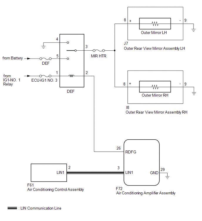
When the mirror heater switch (rear window defogger switch) on the air conditioning control assembly is pressed, the operation signal is sent to the air conditioning amplifier assembly via LIN communication. When the air conditioning amplifier assembly receives the signal, it turns on the defogger relay to operate the mirror heaters.
WIRING DIAGRAM
CAUTION / NOTICE / HINT
NOTICE:
- Inspect the fuses for circuits related to this system before performing the following procedure.
- If the battery voltage is low, the mirror heater function may not operate.
In this case, check the Data List item "Battery Control Count (Body ECU)".
Click here
.gif)
PROCEDURE
|
1. |
PERFORM ACTIVE TEST USING TECHSTREAM |
(a) Connect the Techstream to the DLC3.
(b) Turn the ignition switch to ON.
(c) Turn the Techstream on.
(d) Enter the following menus: Body Electrical / Air Conditioner / Active Test.
(e) Perform the Active Test according to the display on the Techstream.
Body Electrical > Air Conditioner > Active Test|
Tester Display |
Measurement Item |
Control Range |
Diagnostic Note |
|---|---|---|---|
|
Defogger Relay (Rear) |
Mirror Heater |
OFF or ON |
- |
|
Tester Display |
|---|
|
Defogger Relay (Rear) |
|
Result |
Proceed to |
|---|---|
|
Mirror heater operation on both mirrors is not normal |
A |
|
Mirror heater operation on RH side mirror is not normal |
B |
|
Mirror heater operation on LH side mirror is not normal |
C |
| B | .gif) |
GO TO STEP 4 |
| C | |
GO TO STEP 6 |
|
.gif)
|
2. |
CHECK WINDOW DEFOGGER SYSTEM |
(a) Check the window defogger system operation.
Click here
OK:
The window defogger system operates normally.
| NG | |
GO TO WINDOW DEFOGGER SYSTEM |
|
|
3. |
CHECK HARNESS AND CONNECTOR (DEF RELAY - OUTER REAR VIEW MIRROR ASSEMBLY RH/LH - BODY GROUND) |
(a) Remove the DEF relay from the No. 1 engine room relay block.
(b) Disconnect the I8 outer rear view mirror assembly RH connector.
(c) Disconnect the J7 outer rear view mirror assembly LH connector.
(d) Measure the resistance according to the value(s) in the table below.
Standard Resistance:
|
Tester Connection |
Condition |
Specified Condition |
|---|---|---|
|
DEF relay holder terminal-3 - I8-8 (+) |
Always |
Below 1 Ω |
|
DEF relay holder terminal-3 - J7-8 (+) |
Always |
Below 1 Ω |
|
DEF relay holder terminal-3 - Body Ground |
Always |
10 kΩ or higher |
| OK | |
USE SIMULATION METHOD TO CHECK
|
| NG | |
REPAIR OR REPLACE HARNESS OR CONNECTOR |
|
4. |
CHECK HARNESS AND CONNECTOR (DEF RELAY - OUTER REAR VIEW MIRROR ASSEMBLY RH - BODY GROUND) |
(a) Remove the DEF relay from the No. 1 engine room relay block.
(b) Disconnect the I8 outer rear view mirror assembly RH connector.
(c) Disconnect the J7 outer rear view mirror assembly LH connector.
(d) Measure the resistance according to the value(s) in the table below.
Standard Resistance:
|
Tester Connection |
Condition |
Specified Condition |
|---|---|---|
|
DEF relay holder terminal-3 - I8-8 (+) |
Always |
Below 1 Ω |
|
I8-9 (-) - Body Ground |
Always |
Below 1 Ω |
|
I8-8 (+) - Body Ground |
Always |
10 kΩ or higher |
|
DEF relay holder terminal-3 - Body Ground |
Always |
10 kΩ or higher |
| NG | |
REPAIR OR REPLACE HARNESS OR CONNECTOR |
|
|
5. |
INSPECT OUTER MIRROR RH |
(a) Remove the outer mirror RH.
Click here
(b) Inspect the outer mirror RH.
Click here
OK:
Outer rear mirror RH is normal.
| OK | |
REPLACE OUTER REAR VIEW MIRROR ASSEMBLY RH |
| NG | |
REPLACE OUTER MIRROR RH |
|
6. |
CHECK HARNESS AND CONNECTOR (DEF RELAY - OUTER REAR VIEW MIRROR ASSEMBLY LH - BODY GROUND) |
(a) Remove the DEF relay from the No. 1 engine room relay block.
(b) Disconnect the J7 outer rear view mirror assembly LH connector.
(c) Disconnect the I8 outer rear view mirror assembly RH connector.
(d) Measure the resistance according to the value(s) in the table below.
Standard Resistance:
|
Tester Connection |
Condition |
Specified Condition |
|---|---|---|
|
DEF relay holder terminal-3 - J7-8 (+) |
Always |
Below 1 Ω |
|
J7-9 (-) - Body Ground |
Always |
Below 1 Ω |
|
J7-8 (+) - Body Ground |
Always |
10 kΩ or higher |
|
DEF relay holder terminal-3 - Body Ground |
Always |
10 kΩ or higher |
| NG | |
REPAIR OR REPLACE HARNESS OR CONNECTOR |
|
|
7. |
INSPECT OUTER MIRROR LH |
(a) Remove the outer mirror LH.
Click here
(b) Inspect the outer mirror LH.
Click here
OK:
Outer rear mirror LH is normal.
| OK | |
REPLACE OUTER REAR VIEW MIRROR ASSEMBLY LH |
| NG | |
REPLACE OUTER MIRROR LH |
 Data List / Active Test
DATA LIST / ACTIVE TEST
DATA LIST
HINT:
Using the Techstream to read the Data List allows the values or states of switches,
sensors, actuators and other items to be read without removing any part ...
 Power Retractable Mirrors do not Operate with Power Retract Mirror Switch
DESCRIPTION
The outer mirror switch assembly sends a mirror retract/return signal to the
main body ECU (multiplex network body ECU) when the retractable outer mirror switch
on the outer mirror sw ...
Other materials:
Toyota CH-R Service Manual > Audio And Visual System(for Radio And Display Type): USB Device Malfunction (B1585)
DESCRIPTION
This DTC is stored when a malfunction occurs in a connected device.
DTC No.
Detection Item
DTC Detection Condition
Trouble Area
B1585
USB Device Malfunction
USB Device Malfunction
Non mass- ...
Toyota CH-R Owners Manual > Steps to take in an emergency: If your vehicle overheats
The following may indicate that your vehicle is overheating.
The needle of the engine coolant temperature gauge enters the red zone or
a loss of engine power is experienced (for example, the vehicle speed does not
increase).
Steam comes out from under the hood.
Correction procedures
...
Toyota C-HR (AX20) 2023-2026 Owner's Manual
Toyota CH-R Owners Manual
- For safety and security
- Instrument cluster
- Operation of each component
- Driving
- Interior features
- Maintenance and care
- When trouble arises
- Vehicle specifications
- For owners
Toyota CH-R Service Manual
- Introduction
- Maintenance
- Audio / Video
- Cellular Communication
- Navigation / Multi Info Display
- Park Assist / Monitoring
- Brake (front)
- Brake (rear)
- Brake Control / Dynamic Control Systems
- Brake System (other)
- Parking Brake
- Axle And Differential
- Drive Shaft / Propeller Shaft
- K114 Cvt
- 3zr-fae Battery / Charging
- Networking
- Power Distribution
- Power Assist Systems
- Steering Column
- Steering Gear / Linkage
- Alignment / Handling Diagnosis
- Front Suspension
- Rear Suspension
- Tire / Wheel
- Tire Pressure Monitoring
- Door / Hatch
- Exterior Panels / Trim
- Horn
- Lighting (ext)
- Mirror (ext)
- Window / Glass
- Wiper / Washer
- Door Lock
- Heating / Air Conditioning
- Interior Panels / Trim
- Lighting (int)
- Meter / Gauge / Display
- Mirror (int)
- Power Outlets (int)
- Pre-collision
- Seat
- Seat Belt
- Supplemental Restraint Systems
- Theft Deterrent / Keyless Entry

0.0096