Toyota CH-R Service Manual: Removal
REMOVAL
CAUTION / NOTICE / HINT
HINT:
- Use the same procedure for the RH side and LH side.
- The following procedure is for the LH side.
PROCEDURE
1. REMOVE OUTER MIRROR
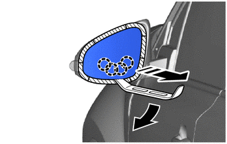
(a) Apply protective tape to the area as shown in the illustration.
.png) |
Protective Tape |
.png) |
Remove in this Direction |
(b) Push the upper part of the mirror surface and tilt it.
(c) Using a moulding remover A, disengage the claws on the lower part of the outer mirror as shown in the illustration.
NOTICE:
Do not push the outer mirror with excessive force. Doing so may cause the actuator to come off or break the mirror surface.
HINT:
If excessive force is used when pressing down the mirror surface, the claws will engage again.
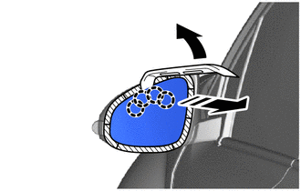
(d) Push the lower part of the mirror surface and tilt it.
HINT:
If excessive force is used when pressing down the mirror surface, the claws will engage again.
(e) Using a moulding remover A, disengage the claws on the upper part of the outer mirror as shown in the illustration.
|
|
Protective Tape |
|
|
Remove in this Direction |
NOTICE:
Do not push the outer mirror with excessive force. Doing so may cause the actuator to come off or break the mirror surface.
HINT:
If excessive force is used when pressing down the mirror surface, the claws will engage again.
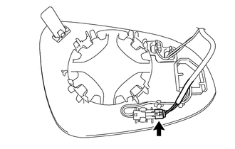
(f) w/ Blind Spot Monitor:
|
(1) Disconnect the connector. |
|
|
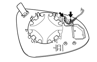
(g) Disconnect the 2 connectors to remove the outer mirror. |
|
 Components
COMPONENTS
ILLUSTRATION
*1
OUTER MIRROR
-
-
...
 Inspection
INSPECTION
PROCEDURE
1. INSPECT OUTER MIRROR LH
(a) Check the resistance.
(1) Measure the resistance according the value(s) in the table below.
Standard Resistance:
...
Other materials:
Toyota CH-R Service Manual > Smart Key System(for Entry Function): Dtc Check / Clear
DTC CHECK / CLEAR
CHECK FOR DTC
NOTICE:
When using the Techstream with the engine switch off, connect the Techstream
to the DLC3 and turn a courtesy light switch on and off at intervals of 1.5 seconds
or less until communication between the Techstream and the vehicle begins. Then
select the ...
Toyota CH-R Service Manual > Automatic High Beam System: Terminals Of Ecu
TERMINALS OF ECU
CHECK INSTRUMENT PANEL JUNCTION BLOCK ASSEMBLY AND MAIN BODY ECU (MULTIPLEX NETWORK
BODY ECU)
*A
Main Body ECU (Multiplex Network Body ECU) with 2 Connectors
-
-
*1
Main Body ECU (Multiplex Network Body EC ...
Toyota C-HR (AX20) 2023-2026 Owner's Manual
Toyota CH-R Owners Manual
- For safety and security
- Instrument cluster
- Operation of each component
- Driving
- Interior features
- Maintenance and care
- When trouble arises
- Vehicle specifications
- For owners
Toyota CH-R Service Manual
- Introduction
- Maintenance
- Audio / Video
- Cellular Communication
- Navigation / Multi Info Display
- Park Assist / Monitoring
- Brake (front)
- Brake (rear)
- Brake Control / Dynamic Control Systems
- Brake System (other)
- Parking Brake
- Axle And Differential
- Drive Shaft / Propeller Shaft
- K114 Cvt
- 3zr-fae Battery / Charging
- Networking
- Power Distribution
- Power Assist Systems
- Steering Column
- Steering Gear / Linkage
- Alignment / Handling Diagnosis
- Front Suspension
- Rear Suspension
- Tire / Wheel
- Tire Pressure Monitoring
- Door / Hatch
- Exterior Panels / Trim
- Horn
- Lighting (ext)
- Mirror (ext)
- Window / Glass
- Wiper / Washer
- Door Lock
- Heating / Air Conditioning
- Interior Panels / Trim
- Lighting (int)
- Meter / Gauge / Display
- Mirror (int)
- Power Outlets (int)
- Pre-collision
- Seat
- Seat Belt
- Supplemental Restraint Systems
- Theft Deterrent / Keyless Entry

0.0108