Toyota CH-R Service Manual: Power Source Circuit
DESCRIPTION
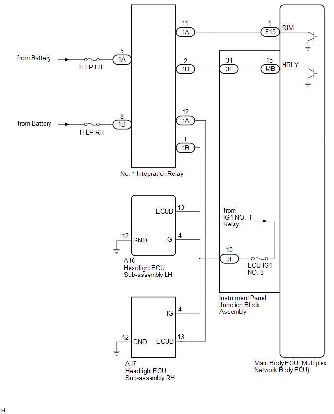
When the ignition switch is ON or the operation conditions of the headlights are met, the main body ECU (multiplex network body ECU) supplies power to the headlight ECU sub-assemblies via the No. 1 integration relay.
When the ignition switch is ON, the main body ECU (multiplex network body ECU) supplies power to the headlight ECU sub-assemblies via the IG1-NO. 1 relay.
WIRING DIAGRAM
CAUTION / NOTICE / HINT
NOTICE:
- Inspect the fuses for circuits related to this system before performing the following inspection procedure.
- Before replacing the main body ECU (multiplex network body ECU), refer
to Registration.*1
Click here
.gif)
- *1: w/ Smart Key System
PROCEDURE
|
1. |
CHECK HARNESS AND CONNECTOR (HEADLIGHT ECU SUB-ASSEMBLY - POWER SOURCE AND BODY GROUND) |
(a) Disconnect the A16 headlight ECU sub-assembly LH connector.
(b) Disconnect the A17 headlight ECU sub-assembly RH connector.
(c) Measure the voltage according to the value(s) in the table below.
Standard Voltage:
Headlight ECU Sub-assembly LH|
Tester Connection |
Switch Condition |
Specified Condition |
|---|---|---|
|
A16-13 (ECUB) - Body ground |
Ignition switch ON |
11 to 14 V |
|
A16-4 (IG) - Body ground |
Ignition switch ON |
11 to 14 V |
|
Tester Connection |
Switch Condition |
Specified Condition |
|---|---|---|
|
A17-13 (ECUB) - Body ground |
Ignition switch ON |
11 to 14 V |
|
A17-4 (IG) - Body ground |
Ignition switch ON |
11 to 14 V |
(d) Measure the resistance according to the value(s) in the table below.
Standard Resistance:
Headlight ECU Sub-assembly LH|
Tester Connection |
Condition |
Specified Condition |
|---|---|---|
|
A16-12 (GND) - Body ground |
Always |
Below 1 Ω |
|
Tester Connection |
Condition |
Specified Condition |
|---|---|---|
|
A17-12 (GND) - Body ground |
Always |
Below 1 Ω |
|
Result |
Proceed to |
|---|---|
|
OK |
A |
|
NG (Headlight ECU Sub-assembly LH) |
B |
|
NG (Headlight ECU Sub-assembly RH) |
C |
| A | .gif) |
PROCEED TO NEXT SUSPECTED AREA SHOWN IN PROBLEM SYMPTOMS TABLE
|
| C | |
GO TO STEP 6 |
|
.gif)
|
2. |
INSPECT NO. 1 INTEGRATION RELAY (H-LP LH RELAY) |
(a) Remove the No. 1 integration relay from the No. 1 engine room relay block.
Click here
(b) Inspect the No. 1 integration relay.
Click here
OK:
No. 1 integration relay is normal.
| NG | |
REPLACE NO. 1 INTEGRATION RELAY |
|
|
3. |
CHECK HARNESS AND CONNECTOR (NO. 1 INTEGRATION RELAY (H-LP LH RELAY) - BATTERY) |
(a) Measure the voltage according to the value(s) in the table below.
Standard Voltage:
|
Tester Connection |
Condition |
Specified Condition |
|---|---|---|
|
1A-5 - Body ground |
Always |
11 to 14 V |
| NG | |
REPAIR OR REPLACE HARNESS OR CONNECTOR |
|
|
4. |
CHECK HARNESS AND CONNECTOR (NO. 1 INTEGRATION RELAY - INSTRUMENT PANEL JUNCTION BLOCK ASSEMBLY) |
(a) Disconnect the 3F instrument panel junction block assembly connector.
(b) Measure the resistance according to the value(s) in the table below.
Standard Resistance:
|
Tester Connection |
Condition |
Specified Condition |
|---|---|---|
|
1B-2 - 3F-31 |
Always |
Below 1 Ω |
|
1B-2 or 3F-31 - Body ground |
Always |
10 kΩ or higher |
| NG | |
REPAIR OR REPLACE HARNESS OR CONNECTOR |
|
|
5. |
INSPECT INSTRUMENT PANEL JUNCTION BLOCK ASSEMBLY |
(a) Remove the instrument panel junction block assembly.
Click here
(b) Remove the main body ECU (multiplex network body ECU) from the instrument panel junction block assembly.
(c) Measure the resistance according to the value(s) in the table below.
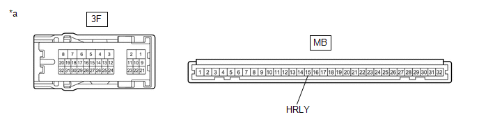
|
*a |
Component without harness connected (Instrument Panel Junction Block Assembly) |
- |
- |
Standard Resistance:
|
Tester Connection |
Condition |
Specified Condition |
|---|---|---|
|
3F-31 - MB-15 (HRLY) |
Always |
Below 1 Ω |
| OK | |
REPLACE MAIN BODY ECU (MULTIPLEX NETWORK BODY ECU)
|
| NG | |
REPLACE INSTRUMENT PANEL JUNCTION BLOCK ASSEMBLY
|
|
6. |
INSPECT NO. 1 INTEGRATION RELAY (H-LP RH RELAY) |
(a) Remove the No. 1 integration relay from the No. 1 engine room relay block.
Click here
(b) Inspect the No. 1 integration relay.
Click here
OK:
No. 1 integration relay is normal.
| NG | |
REPLACE NO. 1 INTEGRATION RELAY |
|
|
7. |
CHECK HARNESS AND CONNECTOR (NO. 1 INTEGRATION RELAY (H-LP RH RELAY) - BATTERY) |
(a) Measure the voltage according to the value(s) in the table below.
Standard Voltage:
|
Tester Connection |
Condition |
Specified Condition |
|---|---|---|
|
1B-8 - Body ground |
Always |
11 to 14 V |
| NG | |
REPAIR OR REPLACE HARNESS OR CONNECTOR |
|
|
8. |
CHECK HARNESS AND CONNECTOR (NO. 1 INTEGRATION RELAY - MAIN BODY ECU (MULTIPLEX NETWORK BODY ECU)) |
(a) Disconnect the F15 main body ECU (multiplex network body ECU) connector.
(b) Measure the resistance according to the value(s) in the table below.
Standard Resistance:
|
Tester Connection |
Condition |
Specified Condition |
|---|---|---|
|
1A-11 - F15-1 (DIM) |
Always |
Below 1 Ω |
|
1A-11 or F15-1 (DIM) - Body ground |
Always |
10 kΩ or higher |
| OK | |
REPLACE MAIN BODY ECU (MULTIPLEX NETWORK BODY ECU)
|
| NG | |
REPAIR OR REPLACE HARNESS OR CONNECTOR |
 Taillight Relay Circuit
DESCRIPTION
The main body ECU (multiplex network body ECU) controls the operation of the
TAIL relay.
WIRING DIAGRAM
CAUTION / NOTICE / HINT
NOTICE:
Inspect the fuses for circuits rela ...
 Low Beam Headlight Circuit
DESCRIPTION
The main body ECU (multiplex network body ECU) controls the low beam headlights.
WIRING DIAGRAM
CAUTION / NOTICE / HINT
NOTICE:
Inspect the fuses and bulbs for circuits rela ...
Other materials:
Toyota CH-R Service Manual > Solar Sensor: Installation
INSTALLATION
PROCEDURE
1. INSTALL AUTOMATIC LIGHT CONTROL SENSOR
(a) Engage the claws to install the automatic light control sensor.
(b) Connect the connector.
2. INSTALL DEFROSTER NOZZLE ASSEMBLY
Click here
3. INSTALL INSTRUM ...
Toyota CH-R Service Manual > Seat Belt: Tongue Plate Stopper
Components
COMPONENTS
ILLUSTRATION
*1
TONGUE PLATE STOPPER
-
-
●
Non-reusable part
-
-
Replacement
REPLACEMENT
PROCEDURE
1. REMOVE TONGUE PLATE STOPPER
(a) Slide the tong ...
Toyota C-HR (AX20) 2023-2026 Owner's Manual
Toyota CH-R Owners Manual
- For safety and security
- Instrument cluster
- Operation of each component
- Driving
- Interior features
- Maintenance and care
- When trouble arises
- Vehicle specifications
- For owners
Toyota CH-R Service Manual
- Introduction
- Maintenance
- Audio / Video
- Cellular Communication
- Navigation / Multi Info Display
- Park Assist / Monitoring
- Brake (front)
- Brake (rear)
- Brake Control / Dynamic Control Systems
- Brake System (other)
- Parking Brake
- Axle And Differential
- Drive Shaft / Propeller Shaft
- K114 Cvt
- 3zr-fae Battery / Charging
- Networking
- Power Distribution
- Power Assist Systems
- Steering Column
- Steering Gear / Linkage
- Alignment / Handling Diagnosis
- Front Suspension
- Rear Suspension
- Tire / Wheel
- Tire Pressure Monitoring
- Door / Hatch
- Exterior Panels / Trim
- Horn
- Lighting (ext)
- Mirror (ext)
- Window / Glass
- Wiper / Washer
- Door Lock
- Heating / Air Conditioning
- Interior Panels / Trim
- Lighting (int)
- Meter / Gauge / Display
- Mirror (int)
- Power Outlets (int)
- Pre-collision
- Seat
- Seat Belt
- Supplemental Restraint Systems
- Theft Deterrent / Keyless Entry

0.0067