Toyota CH-R Service Manual: Headlight Dimmer Switch Circuit
DESCRIPTION
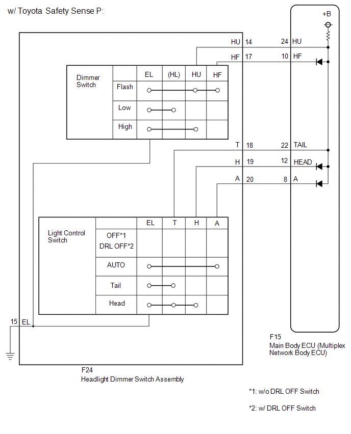
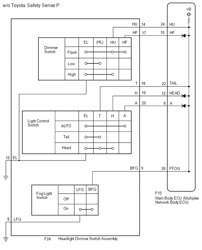
The main body ECU (multiplex network body ECU) receives the following switch information:
- Light control switch in tail, head or AUTO position
- Dimmer switch in high, low or high flash (pass) position
- Fog light switch in front or off position*1
- *1: w/ Fog Light
WIRING DIAGRAM
CAUTION / NOTICE / HINT
NOTICE:
Before replacing the main body ECU (multiplex network body ECU), refer to Registration.*1
Click here
.gif)
- *1: w/ Smart Key System
PROCEDURE
|
1. |
READ VALUE USING TECHSTREAM |
(a) Connect the Techstream to the DLC3.
(b) Turn the ignition switch to ON.
(c) Turn the Techstream on.
(d) Enter the following menus: Body Electrical / Main Body / Data List.
(e) Read the Data List according to the display on the Techstream.
Body Electrical > Main Body > Data List|
Tester Display |
Measurement Item |
Range |
Normal Condition |
Diagnostic Note |
|---|---|---|---|---|
|
Dimmer SW |
Dimmer switch high position signal |
ON or OFF |
ON: Dimmer switch in high or high flash position OFF: Dimmer switch in low position |
- |
|
Passing Light SW |
Dimmer switch high flash position (pass) signal |
ON or OFF |
ON: Dimmer switch in high flash position OFF: Dimmer switch not in high flash position |
- |
|
Front Fog Light SW |
Fog light switch front position signal |
ON or OFF |
ON: Fog light switch in front position OFF: Fog light switch off |
*1 |
|
Auto Light SW |
Light control switch AUTO position signal |
ON or OFF |
ON: Light control switch in AUTO position OFF: Light control switch not in AUTO position |
- |
|
Head Light SW (Head) |
Light control switch head position signal |
ON or OFF |
ON: Light control switch in head position OFF: Light control switch not in head position |
- |
|
Head Light SW (Tail) |
Light control switch tail position signal |
ON or OFF |
ON: Light control switch in tail or head position OFF: Light control switch not in tail or head position |
- |
- *1: w/ Fog Light
|
Tester Display |
|---|
|
Dimmer SW |
|
Passing Light SW |
|
Front Fog Light SW |
|
Auto Light SW |
|
Head Light SW (Head) |
|
Head Light SW (Tail) |
OK:
Normal conditions listed above are displayed.
| OK | .gif) |
PROCEED TO NEXT SUSPECTED AREA SHOWN IN PROBLEM SYMPTOMS TABLE |
|
.gif)
|
2. |
INSPECT HEADLIGHT DIMMER SWITCH ASSEMBLY |
HINT:
Inspect the items that did not change when reading the Data List.
(a) Remove the headlight dimmer switch assembly.
Click here
(b) Inspect the headlight dimmer switch assembly.
Click here
| NG | |
REPLACE HEADLIGHT DIMMER SWITCH ASSEMBLY |
|
|
3. |
CHECK HARNESS AND CONNECTOR (HEADLIGHT DIMMER SWITCH ASSEMBLY - MAIN BODY ECU (MULTIPLEX NETWORK BODY ECU)) |
(a) Disconnect the F15 main body ECU (multiplex network body ECU) connector.
(b) Measure the resistance according to the value(s) in the table below.
Standard Resistance:
|
Tester Connection |
Condition |
Specified Condition |
|---|---|---|
|
F24-9 (BFG) - F15-26 (FFOG)*1 |
Always |
Below 1 Ω |
|
F24-14 (HU) - F15-24 (HU) |
Always |
Below 1 Ω |
|
F24-17 (HF) - F15-10 (HF) |
Always |
Below 1 Ω |
|
F24-18 (T) - F15-22 (TAIL) |
Always |
Below 1 Ω |
|
F24-19 (H) - F15-12 (HEAD) |
Always |
Below 1 Ω |
|
F24-20 (A) - F15-8 (A) |
Always |
Below 1 Ω |
|
F24-9 (BFG) or F15-26 (FFOG) - Body ground*1 |
Always |
10 kΩ or higher |
|
F24-14 (HU) or F15-24 (HU) - Body ground |
Always |
10 kΩ or higher |
|
F24-17 (HF) or F15-10 (HF) - Body ground |
Always |
10 kΩ or higher |
|
F24-18 (T) or F15-22 (TAIL) - Body ground |
Always |
10 kΩ or higher |
|
F24-19 (H) or F15-12 (HEAD) - Body ground |
Always |
10 kΩ or higher |
|
F24-20 (A) or F15-8 (A) - Body ground |
Always |
10 kΩ or higher |
|
F24-15 (EL) - Body ground |
Always |
Below 1 Ω |
|
F24-8 (LFG) - Body ground*1 |
Always |
Below 1 Ω |
*1: w/ Fog Light
| OK | |
REPLACE MAIN BODY ECU (MULTIPLEX NETWORK BODY ECU) |
| NG | |
REPAIR OR REPLACE HARNESS OR CONNECTOR |
 Turn Signal Switch Circuit
DESCRIPTION
The combination meter assembly receives the turn signal switch information and
controls the turn signal lights.
WIRING DIAGRAM
PROCEDURE
1.
READ VALUE USING ...
 Daytime Running Light Relay Circuit
DESCRIPTION
The main body ECU (multiplex network body ECU) controls the daytime running lights.
WIRING DIAGRAM
CAUTION / NOTICE / HINT
NOTICE:
Inspect the fuses for circuits related to ...
Other materials:
Toyota CH-R Service Manual > Shift Lever: Installation
INSTALLATION
PROCEDURE
1. INSTALL FLOOR SHIFT SHIFT LEVER ASSEMBLY
(a) Temporarily install the floor shift shift lever assembly to the body with
the 4 bolts.
(b) Fully tighten the 4 bolts in the order shown in the illustration.
Torque:
12 N·m {122 kgf·cm, 9 ft·lbf}
(c) Engage the 6 cl ...
Toyota CH-R Service Manual > Can Communication System: Check Bus 2 Lines for Short Circuit
DESCRIPTION
There may be a short circuit between the CAN main bus lines and/or CAN branch
lines when the resistance between terminals 18 (CA4H) and 17 (CA4L) of the central
gateway ECU (network gateway ECU) is below 54 Ω.
Symptom
Trouble Area
Resistance ...
Toyota C-HR (AX20) 2023-2026 Owner's Manual
Toyota CH-R Owners Manual
- For safety and security
- Instrument cluster
- Operation of each component
- Driving
- Interior features
- Maintenance and care
- When trouble arises
- Vehicle specifications
- For owners
Toyota CH-R Service Manual
- Introduction
- Maintenance
- Audio / Video
- Cellular Communication
- Navigation / Multi Info Display
- Park Assist / Monitoring
- Brake (front)
- Brake (rear)
- Brake Control / Dynamic Control Systems
- Brake System (other)
- Parking Brake
- Axle And Differential
- Drive Shaft / Propeller Shaft
- K114 Cvt
- 3zr-fae Battery / Charging
- Networking
- Power Distribution
- Power Assist Systems
- Steering Column
- Steering Gear / Linkage
- Alignment / Handling Diagnosis
- Front Suspension
- Rear Suspension
- Tire / Wheel
- Tire Pressure Monitoring
- Door / Hatch
- Exterior Panels / Trim
- Horn
- Lighting (ext)
- Mirror (ext)
- Window / Glass
- Wiper / Washer
- Door Lock
- Heating / Air Conditioning
- Interior Panels / Trim
- Lighting (int)
- Meter / Gauge / Display
- Mirror (int)
- Power Outlets (int)
- Pre-collision
- Seat
- Seat Belt
- Supplemental Restraint Systems
- Theft Deterrent / Keyless Entry

0.01