Toyota CH-R Service Manual: Turn Signal Switch Circuit
DESCRIPTION
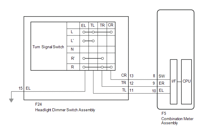
The combination meter assembly receives the turn signal switch information and controls the turn signal lights.
WIRING DIAGRAM
PROCEDURE
|
1. |
READ VALUE USING TECHSTREAM |
(a) Connect the Techstream to the DLC3.
(b) Turn the ignition switch to ON.
(c) Turn the Techstream on.
(d) Enter the following menus: Body Electrical / Combination Meter / Data List.
(e) Read the Data List according to the display on the Techstream.
Body Electrical > Combination Meter > Data List|
Tester Display |
Measurement Item |
Range |
Normal Condition |
Diagnostic Note |
|---|---|---|---|---|
|
Turn Signal Switch (Right) |
Turn signal switch (right) signal |
ON or OFF |
ON: Turn signal switch (right) on OFF: Turn signal switch (right) off |
- |
|
Turn Signal Switch (Left) |
Turn signal switch (left) signal |
ON or OFF |
ON: Turn signal switch (left) on OFF: Turn signal switch (left) off |
- |
|
Turn Switch Signal (Full Turn) |
Turn signal switch (full turn) signal |
ON or OFF |
ON: Turn signal switch (left or right) on OFF: Turn signal switch (left and right) off |
- |
|
Tester Display |
|---|
|
Turn Signal Switch (Right) |
|
Turn Signal Switch (Left) |
|
Turn Switch Signal (Full Turn) |
OK:
Normal conditions listed above are displayed.
| OK | .gif) |
PROCEED TO NEXT SUSPECTED AREA SHOWN IN PROBLEM SYMPTOMS TABLE
|
|
.gif)
|
2. |
INSPECT HEADLIGHT DIMMER SWITCH ASSEMBLY |
(a) Remove the headlight dimmer switch assembly.
Click here
.gif)
(b) Inspect the headlight dimmer switch assembly.
Click here
| NG | |
REPLACE HEADLIGHT DIMMER SWITCH ASSEMBLY |
|
|
3. |
CHECK HARNESS AND CONNECTOR (HEADLIGHT DIMMER SWITCH ASSEMBLY - COMBINATION METER ASSEMBLY OR BODY GROUND) |
(a) Disconnect the F5 combination meter assembly connector.
(b) Measure the resistance according to the value(s) in the table below.
Standard Resistance:
|
Tester Connection |
Condition |
Specified Condition |
|---|---|---|
|
F24-12 (TR) - F5-9 (ER) |
Always |
Below 1 Ω |
|
F24-11 (TL) - F5-10 (EL) |
Always |
Below 1 Ω |
|
F24-13 (CR) - F5-8 (SW) |
Always |
Below 1 Ω |
|
F24-12 (TR) or F5-9 (ER) - Body ground |
Always |
10 kΩ or higher |
|
F24-11 (TL) or F5-10 (EL) - Body ground |
Always |
10 kΩ or higher |
|
F24-13 (CR) or F5-8 (SW) - Body ground |
Always |
10 kΩ or higher |
|
F24-15 (EL) - Body ground |
Always |
Below 1 Ω |
| OK | |
PROCEED TO NEXT SUSPECTED AREA SHOWN IN PROBLEM SYMPTOMS TABLE
|
| NG | |
REPAIR OR REPLACE HARNESS OR CONNECTOR |
 CAN Communication Failure (Message Registry) (U1000)
DESCRIPTION
The headlight ECU sub-assembly LH stores this DTC if it detects an internal malfunction
related to the CAN communication system.
DTC No.
Detection Item
...
 Headlight Dimmer Switch Circuit
DESCRIPTION
The main body ECU (multiplex network body ECU) receives the following switch
information:
Light control switch in tail, head or AUTO position
Dimmer switch in high, low or h ...
Other materials:
Toyota CH-R Service Manual > Seat Belt Warning System(w/o Occupant Classification System): Parts Location
PARTS LOCATION
ILLUSTRATION
*1
BRAKE ACTUATOR ASSEMBLY (SKID CONTROL ECU)
*2
ECM
ILLUSTRATION
*1
MAIN BODY ECU (MULTIPLEX NETWORK BODY ECU)
*2
INSTRUMENT PANEL JUNCTION BLOCK ASSEMBLY
- ECU-DC ...
Toyota CH-R Service Manual > Fog Light Assembly: Removal
REMOVAL
CAUTION / NOTICE / HINT
HINT:
Use the same procedure for the RH side and LH side.
The following procedure is for the LH side.
PROCEDURE
1. REMOVE FRONT BUMPER ASSEMBLY
Click here
2. REMOVE FOG LIGHT ASSEMBLY
(a) Remove the 2 screws.
...
Toyota C-HR (AX20) 2023-2026 Owner's Manual
Toyota CH-R Owners Manual
- For safety and security
- Instrument cluster
- Operation of each component
- Driving
- Interior features
- Maintenance and care
- When trouble arises
- Vehicle specifications
- For owners
Toyota CH-R Service Manual
- Introduction
- Maintenance
- Audio / Video
- Cellular Communication
- Navigation / Multi Info Display
- Park Assist / Monitoring
- Brake (front)
- Brake (rear)
- Brake Control / Dynamic Control Systems
- Brake System (other)
- Parking Brake
- Axle And Differential
- Drive Shaft / Propeller Shaft
- K114 Cvt
- 3zr-fae Battery / Charging
- Networking
- Power Distribution
- Power Assist Systems
- Steering Column
- Steering Gear / Linkage
- Alignment / Handling Diagnosis
- Front Suspension
- Rear Suspension
- Tire / Wheel
- Tire Pressure Monitoring
- Door / Hatch
- Exterior Panels / Trim
- Horn
- Lighting (ext)
- Mirror (ext)
- Window / Glass
- Wiper / Washer
- Door Lock
- Heating / Air Conditioning
- Interior Panels / Trim
- Lighting (int)
- Meter / Gauge / Display
- Mirror (int)
- Power Outlets (int)
- Pre-collision
- Seat
- Seat Belt
- Supplemental Restraint Systems
- Theft Deterrent / Keyless Entry

0.0124