Toyota CH-R Service Manual: Adjustment
ADJUSTMENT
PROCEDURE
1. PREPARE VEHICLE FOR HEADLIGHT AIM ADJUSTMENT
(a) Prepare the vehicle:
- Ensure that there is no damage or deformation to the vehicle body around the headlights.
- Fill the fuel tank.
- Make sure that the oil is filled to the specified level.
- Make sure that the engine coolant is filled to the specified level.
- Inflate the tires to the appropriate pressure.
- Unload the trunk and vehicle, ensuring that the spare tire, tools and jack are in their original positions.
- Bounce the vehicle at the corners up and down to stabilize the suspension.
- Sit a person of average weight (75 kg, 165 lb) in the driver's seat.
2. PREPARE FOR HEADLIGHT AIMING (Using a screen)
(a) Prepare the vehicle:
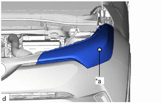
.png)
|
*a |
Center Mark |
- Place the vehicle in a location that is dark enough to clearly observe the cutoff line. The cutoff line is a distinct line, below which light from the headlights can be observed and above which it cannot.
- Place the vehicle at a 90° angle to the wall.
- Create a 25 m (82 ft.) distance between the vehicle (center marks of the headlights) and the wall.
- Make sure that the vehicle is on a level surface.
- Position the front wheels straight ahead.
- Bounce the vehicle up and down to settle the suspension.
NOTICE:
A distance of 25 m (82 ft.) between the vehicle (center marks of the headlights) and the wall is necessary for proper aim adjustment. If sufficient space is not available, secure a distance of exactly 3 m (9.84 ft.) to allow for checking and adjustment of headlight aim. (The size of the target zone will change with the distance, so follow the instructions in the illustration.)
(b) Prepare a piece of thick white paper (approximately 2 m (6.56 ft.) (height) x 4 m (13.1 ft.) (width)) to use as a screen.
(c) Draw a vertical line down the center of the screen (V line).
(d) Set the screen as shown in the illustration:
.png)
HINT:
- Stand the screen perpendicular to the ground.
- Align the V line on the screen with the center of the vehicle.
(e) Draw base lines (H, V LH, and V RH lines) on the screen as shown in the illustration.
.png)
|
*a |
V LH Line |
|
*b |
V Line |
|
*c |
V RH Line |
|
*d |
H Line |
|
*e |
Ground |
HINT:
Mark the headlight center marks on the screen.
|
*a |
Center Mark |
(1) H Line (Headlight height):
Draw a horizontal line across the screen so that it passes through the center marks. The H line should be at the same height as the center marks of the headlights.
(2) V LH Line, V RH Line (Center mark position of left-hand (LH) and right-hand (RH) headlights):
Draw 2 vertical lines so that they intersect the H line at each center mark (aligned with the center marks of the headlights).
3. INSPECT HEADLIGHT AIMING
(a) Cover the headlight on the opposite side to prevent light from the headlight that is not being inspected from affecting the headlight aiming inspection.
NOTICE:
Do not keep the headlight covered for more than 3 minutes. The headlight lens is made of synthetic resin, which may melt or be damaged due to excessive heat.
(b) Start the engine.
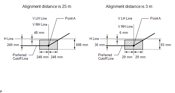
(c) Turn on the headlights and check if the cutoff line for each low beam matches the preferred cutoff line in the illustration.
HINT:
- Since the low beam light and the high beam light are a unit, if the aim on the low beam is correct, the high beam should also be correct. However, check both beams just to make sure.
- If the alignment distance is 25 m (82 ft.):
The low beam cutoff line should be between 48 mm (1.89 in.) and 698 mm (2.29 ft.) below the H line as well as 248 mm (9.79 in.) left or right of the V LH or V RH line.
- If the alignment distance is 3 m (9.84 ft.):
The low beam cutoff line should be between 6 mm (0.227 in.) and 83 mm (3.29 in.) below the H line as well as 29 mm (1.17 in.) left or right of the V LH or V RH line.
- If the alignment distance is 25 m (82 ft.):
The horizontal line of the preferred low beam cutoff line is 249 mm (9.79 in.) below the H line and point A of the preferred low beam cutoff line is on the V LH or V RH line.
- If the alignment distance is 3 m (9.84 ft.):
The horizontal line of the preferred low beam cutoff line is 30 mm (1.18 in.) below the H line and point A of the preferred low beam cutoff line is on the V LH or V RH line.
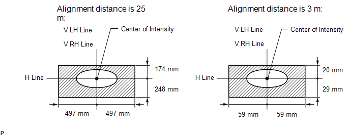
(d) Turn on the high beams and check if the center of intensity for each high beam matches the preferred center of the intensity in the illustration.
HINT:
- Since the low beam light and the high beam light are a unit, if the aim on the low beam is correct, the high beam should also be correct. However, check both beams just to make sure.
- If the alignment distance is 25 m (82 ft.):
The high beam center of intensity should be within 174 mm (6.87 in.) above and 248 mm (9.79 in.) below the H line as well as 497 mm (1.63 ft.) left or right of the V LH or V RH line.
- If the alignment distance is 3 m (9.84 ft.):
The high beam center of intensity should be within 20 mm (0.824 in.) above and 29 mm (1.17 in.) below the H line as well as 59 mm (2.35 in.) left or right of the V LH or V RH line.
4. ADJUST HEADLIGHT AIMING
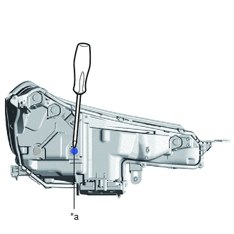
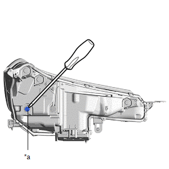
(a) Adjust the aim vertically:
|
(1) Adjust the aim of each headlight to the specified range by turning each aiming screw (A) with a screwdriver. NOTICE: The final turn of the aiming screw should be made in the clockwise direction. If the screw is tightened excessively, loosen it and then retighten it, so that the final turn of the screw is in the clockwise direction. HINT:
|
|
(b) Adjust the aim horizontally:
|
(1) Adjust the aim of each headlight to the specified range by turning each aiming screw (B) with a screwdriver. NOTICE: The final turn of the aiming screw should be made in the clockwise direction. If the screw is tightened excessively, loosen it and then retighten it, so that the final turn of the screw is in the clockwise direction. HINT:
|
|
 Disassembly
DISASSEMBLY
CAUTION / NOTICE / HINT
HINT:
Use the same procedure for the RH side and LH side.
The following procedure is for the LH side.
PROCEDURE
1. REMOVE HEADLIGHT PROTECTOR ...
 Installation
INSTALLATION
CAUTION / NOTICE / HINT
HINT:
Use the same procedure for the RH side and LH side.
The following procedure is for the LH side.
PROCEDURE
1. INSTALL HEADLIGHT ASSEMBL ...
Other materials:
Toyota CH-R Service Manual > Front Door: Adjustment
ADJUSTMENT
CAUTION / NOTICE / HINT
*a
Centering Bolt
*b
Standard Bolt
HINT:
Use the same procedure for the RH side and LH side.
The following procedure is for the LH side.
Centering bolts are used to install the door hi ...
Toyota CH-R Service Manual > Pre-collision System: Skid Control Buzzer Circuit (C1A4A)
DESCRIPTION
The millimeter wave radar sensor assembly is connected to the forward recognition
camera via CAN communication.
The millimeter wave radar sensor assembly operates the pre-collision alarm by
sending a buzzer request signal to the pre-collision city buzzer.
If the millimeter wave ra ...
Toyota C-HR (AX20) 2023-2026 Owner's Manual
Toyota CH-R Owners Manual
- For safety and security
- Instrument cluster
- Operation of each component
- Driving
- Interior features
- Maintenance and care
- When trouble arises
- Vehicle specifications
- For owners
Toyota CH-R Service Manual
- Introduction
- Maintenance
- Audio / Video
- Cellular Communication
- Navigation / Multi Info Display
- Park Assist / Monitoring
- Brake (front)
- Brake (rear)
- Brake Control / Dynamic Control Systems
- Brake System (other)
- Parking Brake
- Axle And Differential
- Drive Shaft / Propeller Shaft
- K114 Cvt
- 3zr-fae Battery / Charging
- Networking
- Power Distribution
- Power Assist Systems
- Steering Column
- Steering Gear / Linkage
- Alignment / Handling Diagnosis
- Front Suspension
- Rear Suspension
- Tire / Wheel
- Tire Pressure Monitoring
- Door / Hatch
- Exterior Panels / Trim
- Horn
- Lighting (ext)
- Mirror (ext)
- Window / Glass
- Wiper / Washer
- Door Lock
- Heating / Air Conditioning
- Interior Panels / Trim
- Lighting (int)
- Meter / Gauge / Display
- Mirror (int)
- Power Outlets (int)
- Pre-collision
- Seat
- Seat Belt
- Supplemental Restraint Systems
- Theft Deterrent / Keyless Entry

0.0065