Toyota CH-R Service Manual: Parts Location
PARTS LOCATION
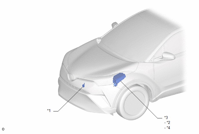
ILLUSTRATION
|
*1 |
LOW PITCHED HORN ASSEMBLY |
*2 |
HORN RELAY |
|
*3 |
NO. 1 ENGINE ROOM RELAY BLOCK |
*4 |
HORN FUSE |
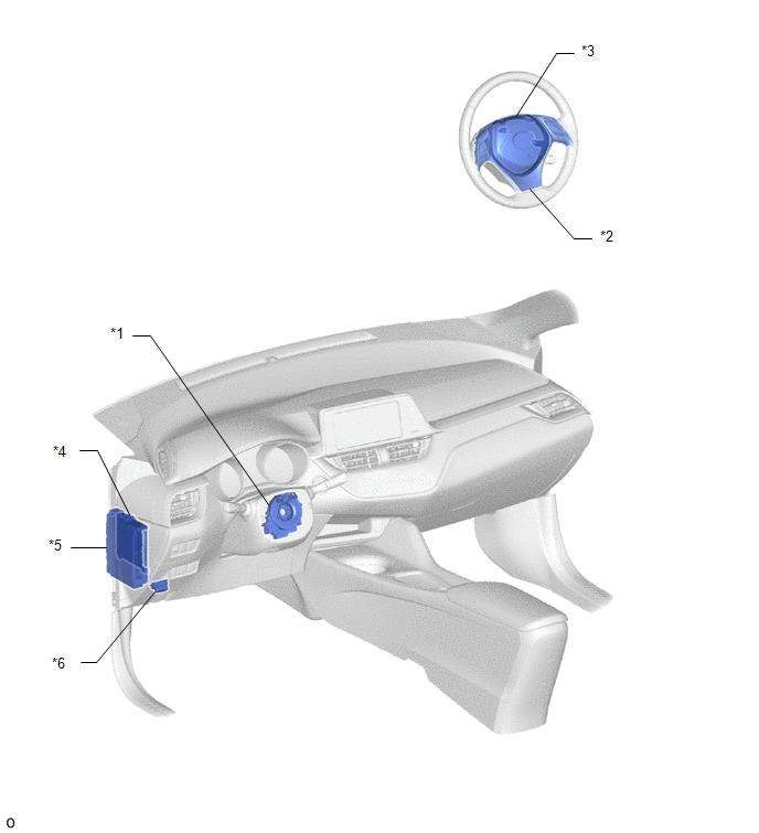
ILLUSTRATION
|
*1 |
SPIRAL CABLE SUB-ASSEMBLY |
*2 |
STEERING PAD SWITCH ASSEMBLY |
|
*3 |
HORN BUTTON ASSEMBLY |
*4 |
MAIN BODY ECU (MULTIPLEX NETWORK BODY ECU) |
|
*5 |
INSTRUMENT PANEL JUNCTION BLOCK ASSEMBLY |
*6 |
DLC3 |
 Precaution
PRECAUTION
IGNITION SWITCH EXPRESSION
HINT:
The type of ignition switch used on this model differs according to the specifications
of the vehicle. The expressions listed in the table below are us ...
 Problem Symptoms Table
PROBLEM SYMPTOMS TABLE
HINT:
Use the table below to help determine the cause of problem symptoms. If multiple
suspected areas are listed, the potential causes of the symptoms are listed in order
...
Other materials:
Toyota CH-R Service Manual > Audio And Visual System(for Radio And Display Type): Speaker Circuit
DESCRIPTION
If there is a short in a speaker circuit, the radio and display receiver assembly
detects it and stops output to the speakers.
Thus sound cannot be heard from the speakers even if there is no malfunction
in the radio and display receiver assembly, DCM (telematics transceiver)*1 or ...
Toyota CH-R Service Manual > Safety Connect System: Short in Telephone SUB Antenna Circuit (B1536,B1537)
DESCRIPTION
These DTCs are stored when the DCM (Telematics Transceiver) detects an open or
a short in the telephone and GPS antenna assembly (for Front Side) circuit. The
DCM (Telematics Transceiver) oscillates and receives 824 - 894 MHz or 1850 - 1990
MHz radio-frequency through the telephon ...
Toyota C-HR (AX20) 2023-2026 Owner's Manual
Toyota CH-R Owners Manual
- For safety and security
- Instrument cluster
- Operation of each component
- Driving
- Interior features
- Maintenance and care
- When trouble arises
- Vehicle specifications
- For owners
Toyota CH-R Service Manual
- Introduction
- Maintenance
- Audio / Video
- Cellular Communication
- Navigation / Multi Info Display
- Park Assist / Monitoring
- Brake (front)
- Brake (rear)
- Brake Control / Dynamic Control Systems
- Brake System (other)
- Parking Brake
- Axle And Differential
- Drive Shaft / Propeller Shaft
- K114 Cvt
- 3zr-fae Battery / Charging
- Networking
- Power Distribution
- Power Assist Systems
- Steering Column
- Steering Gear / Linkage
- Alignment / Handling Diagnosis
- Front Suspension
- Rear Suspension
- Tire / Wheel
- Tire Pressure Monitoring
- Door / Hatch
- Exterior Panels / Trim
- Horn
- Lighting (ext)
- Mirror (ext)
- Window / Glass
- Wiper / Washer
- Door Lock
- Heating / Air Conditioning
- Interior Panels / Trim
- Lighting (int)
- Meter / Gauge / Display
- Mirror (int)
- Power Outlets (int)
- Pre-collision
- Seat
- Seat Belt
- Supplemental Restraint Systems
- Theft Deterrent / Keyless Entry

0.0085