Toyota CH-R Service Manual: Reassembly
REASSEMBLY
PROCEDURE
1. INSTALL NO. 1 REAR SPOILER PROTECTOR
HINT:
- Using the same procedure, install every No. 1 rear spoiler protector.
- When installing the No. 1 rear spoiler protector, heat the rear spoiler assembly using a heat light.
|
Item |
Temperature |
|---|---|
|
Rear Spoiler Assembly |
20 to 30°C (68 to 86°F) |
CAUTION:
- Do not touch the heat light and heated parts, touching the heat light may result in burns.
- Touching heated parts for a long time may result in burns.
.png)
|
*a |
Heated Part |
|
*b |
Heat Light |
NOTICE:
Do not heat the rear spoiler assembly excessively.
(a) Clean the rear spoiler assembly surface.
(1) Using a heat light, heat the rear spoiler assembly surface.
(2) Remove the double-sided tape from the rear spoiler assembly.
(3) Wipe off any tape adhesive residue with cleaner.
(b) Using a heat light, heat the rear spoiler assembly.
(c) Remove the release paper from a new No. 1 rear spoiler protector.
HINT:
After removing the release paper, keep the exposed adhesive free from foreign matter.
|
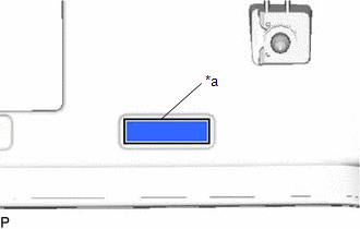
(d) Install the No. 1 rear spoiler protector as shown in the illustration. HINT: Install the No. 1 rear spoiler protector along the line on the rear spoiler assembly. |
|
2. INSTALL CENTER STOP LIGHT CORD ASSEMBLY
|
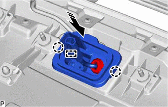
(a) Engage the guides to install the center stop light cord assembly. |
|
.png)
3. INSTALL REAR SIDE SPOILER SUB-ASSEMBLY
|
(a) Engage the guide to install the No. 5 rear spoiler retainer. |
|
.png)
(b) Install the screw.
(c) Engage the guide and claws to install the rear side spoiler sub-assembly as shown in the illustration.
.png) |
Install in this Direction |
4. INSTALL CENTER STOP LIGHT ASSEMBLY
Click here
.gif)
5. INSTALL NO. 2 REAR SPOILER PROTECTOR
HINT:
- Using the same procedure, install every No. 2 rear spoiler protector.
- When installing the No. 2 rear spoiler protector, heat the rear spoiler using a heat light.
|
Item |
Temperature |
|---|---|
|
Rear Spoiler Assembly |
20 to 30°C (68 to 86°F) |
CAUTION:
- Do not touch the heat light and heated parts, touching the heat light may result in burns.
- Touching heated parts for a long time may result in burns.
|
*a |
Heated Part |
|
*b |
Heat Light |
NOTICE:
Do not heat the rear spoiler assembly excessively.
(a) Clean the rear spoiler assembly surface.
(1) Using a heat light, heat the rear spoiler assembly surface.
(2) Remove the double-sided tape from the rear spoiler assembly.
(3) Wipe off any tape adhesive residue with cleaner.
(b) Using a heat light, heat the rear spoiler assembly.
(c) Remove the release paper from new No. 2 rear spoiler protector.
HINT:
After removing the release paper, keep the exposed adhesive free from foreign matter.
|
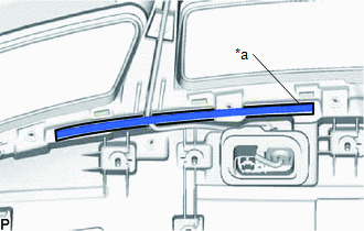
(d) Install the No. 2 rear spoiler protector as shown in the illustration. HINT: Install each No. 2 rear spoiler protector along the line on the rear spoiler assembly. |
|
6. INSTALL NO. 2 REAR SPOILER
(a) Engage the claws to install the No. 2 rear spoiler as shown in the illustration.
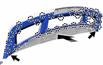
|
|
Install in this Direction |
(b) Install the 2 screws.
 Disassembly
DISASSEMBLY
PROCEDURE
1. REMOVE NO. 2 REAR SPOILER
(a) Remove the 2 screws.
Remove in this Direction
(b) Disengage the claws to remove the No. 2 rear spoiler as sho ...
 Installation
INSTALLATION
PROCEDURE
1. INSTALL REAR SPOILER ASSEMBLY
(a) Engage the clips to install the rear spoiler assembly as shown in the illustration.
Install in this Direction
...
Other materials:
Toyota CH-R Service Manual > Front Brake: Components
COMPONENTS
ILLUSTRATION
*1
FRONT DISC BRAKE ANTI-SQUEAL SHIM KIT
*2
FRONT DISC BRAKE CYLINDER ASSEMBLY
*3
FRONT DISC BRAKE PAD
*4
FRONT FLEXIBLE HOSE
*5
FRONT DISC BRAKE ANTI ...
Toyota CH-R Service Manual > Knee Airbag Assembly: Installation
INSTALLATION
PROCEDURE
1. INSTALL LOWER NO. 1 INSTRUMENT PANEL AIRBAG DOOR (for TMMT Made)
(a) Engage the hooks.
(b) Engage the hooks to install the lower No. 1 instrument panel airbag
door to the lower No. 1 instrument pan ...
Toyota C-HR (AX20) 2023-2026 Owner's Manual
Toyota CH-R Owners Manual
- For safety and security
- Instrument cluster
- Operation of each component
- Driving
- Interior features
- Maintenance and care
- When trouble arises
- Vehicle specifications
- For owners
Toyota CH-R Service Manual
- Introduction
- Maintenance
- Audio / Video
- Cellular Communication
- Navigation / Multi Info Display
- Park Assist / Monitoring
- Brake (front)
- Brake (rear)
- Brake Control / Dynamic Control Systems
- Brake System (other)
- Parking Brake
- Axle And Differential
- Drive Shaft / Propeller Shaft
- K114 Cvt
- 3zr-fae Battery / Charging
- Networking
- Power Distribution
- Power Assist Systems
- Steering Column
- Steering Gear / Linkage
- Alignment / Handling Diagnosis
- Front Suspension
- Rear Suspension
- Tire / Wheel
- Tire Pressure Monitoring
- Door / Hatch
- Exterior Panels / Trim
- Horn
- Lighting (ext)
- Mirror (ext)
- Window / Glass
- Wiper / Washer
- Door Lock
- Heating / Air Conditioning
- Interior Panels / Trim
- Lighting (int)
- Meter / Gauge / Display
- Mirror (int)
- Power Outlets (int)
- Pre-collision
- Seat
- Seat Belt
- Supplemental Restraint Systems
- Theft Deterrent / Keyless Entry

0.0073