Toyota CH-R Service Manual: All Door Entry Lock/Unlock Functions do not Operate, but Wireless Functions Operate
DESCRIPTION
When the wireless operation can be used to lock and unlock the doors, communication between the electrical key and TPMS receiver assembly and certification ECU (smart key ECU assembly) is normal. If the entry lock and unlock functions do not operate, the entry cancel function may be set through the customize function, there may be communication problems between the electrical key transmitter sub-assembly and vehicle, or there may be wave interference.
CAUTION / NOTICE / HINT
NOTICE:
- The smart key system (for Entry Function) uses the LIN communication
system and CAN communication system. Inspect the communication function
by following How to Proceed with Troubleshooting. Troubleshoot the smart
key system (for Entry Function) after confirming that the communication
systems are functioning properly.
Click here
.gif)
- When using the Techstream with the engine switch off, connect the Techstream to the DLC3 and turn a courtesy light switch on and off at intervals of 1.5 seconds or less until communication between the Techstream and the vehicle begins. Then select the vehicle type under manual mode and enter the following menus: Body Electrical / Smart Key. While using the Techstream, periodically turn a courtesy light switch on and off at intervals of 1.5 seconds or less to maintain communication between the Techstream and the vehicle.
- Check that there are no electrical key transmitter sub-assemblies in the vehicle.
- Before performing the inspection, check that DTC B1242 (wireless door
lock control) is not output.
Click here
- Before replacing the certification ECU (smart key ECU assembly) or electrical
key transmitter sub-assembly, refer to Precaution.
Click here
- After repair, confirm that no DTCs are output.
PROCEDURE
|
1. |
CHECK POWER DOOR LOCK CONTROL SYSTEM |
(a) When the door control switch on the multiplex network master switch assembly is operated, check that the doors unlock and lock according to the switch operation.
Click here
OK:
Door locks operate normally.
| NG | .gif) |
GO TO POWER DOOR LOCK CONTROL SYSTEM |
|
.gif)
|
2. |
CHECK WAVE ENVIRONMENT |
(a) Move the electrical key transmitter sub-assembly as described below and perform the operation inspection.
HINT:
- When the electrical key transmitter sub-assembly is brought near the front door outside handle assembly LH or electrical key antenna (outside luggage compartment), the possibility of wave interference decreases, and it can be determined if wave interference is causing the problem symptom.
- If the inspection result is that the problem only occurs in certain locations or at certain times of day, the possibility of wave interference is high. Also, added vehicle components may cause wave interference. If installed, remove them and perform the operation check.
- There may be wave interference if the vehicle is near broadcasting antennas, large video displays, wireless garage door opener systems, wireless security cameras, home security systems, etc. In this case, move the vehicle to a different location and check if there is any improvement.
- If a tool for checking radio waves, such as a signal strength meter, is available, move around the area while observing both the LF band (used by the vehicle antenna to form the detection area) and RF band (used by the electrical key transmitter sub-assembly for transmission) to check for locations where there is wave interference.
- The transmitting wave of the wireless function and entry function are the same, but the wave logic is different. As a result, it is possible that only the wireless function or only the entry function is affected by wave interference.
|
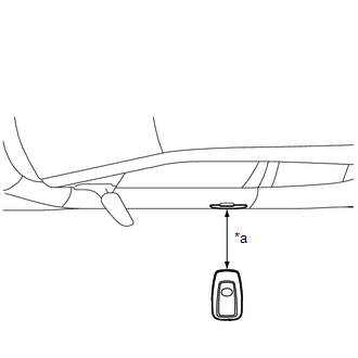
(1) Bring the electrical key transmitter sub-assembly approximately 0.7 to 1 m (2.30 to 3.28 ft.) from the front door outside handle assembly LH and perform a driver door entry lock and unlock operation check. HINT: Communication may not be possible if the electrical key transmitter sub-assembly is within 0.2 m (0.656 ft.) of the door handle. |
|

|
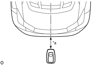
(2) Bring the electrical key transmitter sub-assembly approximately 0.7 to 1 m (2.30 to 3.28 ft.) from the front door outside handle assembly RH and perform a front passenger door entry lock and unlock operation check. HINT: Communication may not be possible if the electrical key transmitter sub-assembly is within 0.2 m (0.656 ft.) of the door handle. |
|
|
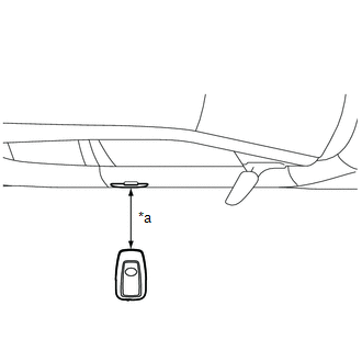
(3) Bring the electrical key transmitter sub-assembly approximately 0.7 to 1 m (2.30 to 3.28 ft.) from the electrical key antenna (outside luggage compartment) and perform an entry back door open function check. HINT: Communication may not be possible if the electrical key transmitter sub-assembly is within 0.2 m (0.656 ft.) of the rear bumper. |
|
|
Result |
Proceed to |
|---|---|
|
All operation checks fail |
A |
|
All operation checks are normal |
B |
|
Some operation checks are normal |
C |
| B | |
AFFECTED BY WAVE INTERFERENCE |
| C | |
GO TO OTHER PROBLEM |
|
|
3. |
CHECK KEY DIAGNOSTIC MODE |
(a) Check the following antennas in key diagnostic mode.
Body Electrical > Smart Key > Utility|
Tester Display |
|---|
|
Communication Check(Key Diag Mode) |
(b) Select either channel 1 or channel 2 and perform key diagnostic mode inspection for each channel).
|
(1) Check the electrical key antenna (for driver door): When the electrical key transmitter sub-assembly is brought within 0.7 to 1 m (2.30 to 3.28 ft.) of the front door outside handle assembly LH, check that the wireless buzzer sounds. HINT:
|
|
|
(2) Check the electrical key antenna (for front passenger door): When the electrical key transmitter sub-assembly is brought within 0.7 to 1 m (2.30 to 3.28 ft.) of the front door outside handle assembly RH, check that the wireless buzzer sounds. HINT:
|
|

|
(3) Check the electrical key antenna (outside luggage compartment): When the electrical key transmitter sub-assembly is brought within 0.7 to 1 m (2.30 to 3.28 ft.) of the electrical key antenna (outside luggage compartment), check that the wireless buzzer sounds. HINT:
OK: Wireless buzzer sounds. |
|

|
Result |
Proceed to |
|---|---|
|
All diagnostic mode inspections fail |
A |
|
Some diagnostic mode inspections fail (door) |
B |
|
Some diagnostic mode inspections fail (outside luggage compartment) |
C |
|
All diagnostic mode inspections are normal |
D |
| B | |
GO TO OTHER PROBLEM |
| C | |
GO TO OTHER PROBLEM |
| D | |
REPLACE CERTIFICATION ECU (SMART KEY ECU ASSEMBLY) |
|
|
4. |
CHECK ELECTRICAL KEY TRANSMITTER SUB-ASSEMBLY |
(a) Check if there is another electrical key transmitter sub-assembly available that is already registered to the vehicle.
|
Result |
Proceed to |
|---|---|
|
Another registered electrical key transmitter sub-assembly is not available |
A |
|
Another registered electrical key transmitter sub-assembly is available |
B |
| B | |
GO TO STEP 6 |
|
|
5. |
ELECTRICAL KEY TRANSMITTER SUB-ASSEMBLY REGISTRATION (NEW ELECTRICAL KEY TRANSMITTER SUB-ASSEMBLY) |
(a) Register a new electrical key transmitter sub-assembly.
HINT:
Refer to Registration.
Click here
|
|
6. |
CHECK ENTRY LOCK OPERATION |
(a) Using another registered electrical key transmitter sub-assembly, check that the entry function operates normally.
Click here
|
Result |
Proceed to |
|---|---|
|
Entry function operates normally |
A |
|
Entry function does not operate normally |
B |
| A | |
END (ELECTRICAL KEY TRANSMITTER SUB-ASSEMBLY WAS DEFECTIVE) |
| B | |
REPLACE CERTIFICATION ECU (SMART KEY ECU ASSEMBLY) |
 All Door Entry Lock/Unlock Functions and Wireless Functions do not Operate
DESCRIPTION
If the entry lock and wireless door lock operations cannot be performed, the
electrical key and TPMS receiver assembly may be malfunctioning, or there may be
wave interference or prob ...
 Driver Side Door Entry Unlock Function does not Operate
DESCRIPTION
If the entry unlock function does not operate for the driver door only, but the
entry lock function operates, the request code is being transmitted properly from
the driver door. In t ...
Other materials:
Toyota CH-R Service Manual > Air Conditioning System(for Automatic Air Conditioning System With Top-mounted
Air Conditioner Pressure Sensor): System Diagram
SYSTEM DIAGRAM
Communication Table
Sender
Receiver
Signal
Communication Line
Air conditioning amplifier assembly
ECM
Magnet Clutch request signal
CAN
A/C idle up request si ...
Toyota CH-R Service Manual > Blind Spot Monitor System: Short to GND or Open in Buzzer (C1ABE)
DESCRIPTION
DTC C1ABE is stored when the blind spot monitor sensor RH (Slave) detects
a short to ground or open in the RCTA buzzer (blind spot monitor buzzer)
circuit.
DTC No.
Detection Item
DTC Detection Condition
Trouble Area
...
Toyota C-HR (AX20) 2023-2025 Owner's Manual
Toyota CH-R Owners Manual
- For safety and security
- Instrument cluster
- Operation of each component
- Driving
- Interior features
- Maintenance and care
- When trouble arises
- Vehicle specifications
- For owners
Toyota CH-R Service Manual
- Introduction
- Maintenance
- Audio / Video
- Cellular Communication
- Navigation / Multi Info Display
- Park Assist / Monitoring
- Brake (front)
- Brake (rear)
- Brake Control / Dynamic Control Systems
- Brake System (other)
- Parking Brake
- Axle And Differential
- Drive Shaft / Propeller Shaft
- K114 Cvt
- 3zr-fae Battery / Charging
- Networking
- Power Distribution
- Power Assist Systems
- Steering Column
- Steering Gear / Linkage
- Alignment / Handling Diagnosis
- Front Suspension
- Rear Suspension
- Tire / Wheel
- Tire Pressure Monitoring
- Door / Hatch
- Exterior Panels / Trim
- Horn
- Lighting (ext)
- Mirror (ext)
- Window / Glass
- Wiper / Washer
- Door Lock
- Heating / Air Conditioning
- Interior Panels / Trim
- Lighting (int)
- Meter / Gauge / Display
- Mirror (int)
- Power Outlets (int)
- Pre-collision
- Seat
- Seat Belt
- Supplemental Restraint Systems
- Theft Deterrent / Keyless Entry

0.0138