Toyota CH-R Service Manual: Reassembly
REASSEMBLY
CAUTION / NOTICE / HINT
HINT:
- Use the same procedure for the RH side and LH side.
- The following procedure is for the LH side.
PROCEDURE
1. INSTALL QUARTER GARNISH MOULDING
HINT:
When installing the quarter garnish moulding, heat the quarter pillar cover sub-assembly using a heat light.
Heating Temperature|
Item |
Temperature |
|---|---|
|
Quarter Pillar Cover Sub-assembly |
20 to 30°C (68 to 86°F) |
CAUTION:
- Do not touch the heat light and heated parts, touching the heat light may result in burns.
- Touching heated parts for a long time may result in burns.
.png)
|
*a |
Heated Part |
|
*b |
Heat Light |
NOTICE:
Do not heat the quarter pillar cover sub-assembly excessively.
(a) Clean the quarter pillar cover sub-assembly surface.
(1) Using a heat light, heat the quarter pillar cover sub-assembly surface.
(2) Remove the double-sided tape from the quarter pillar cover sub-assembly.
(3) Wipe off any tape adhesive residue with cleaner.
(b) Using a heat light, heat the quarter pillar cover sub-assembly.
(c) Remove the release paper from a new quarter garnish moulding.
HINT:
After removing the release paper, keep the exposed adhesive free from foreign matter.
|
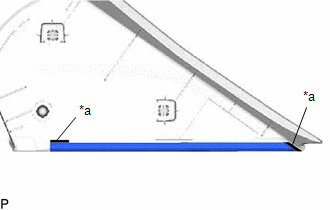
(d) Install the quarter garnish moulding as shown in the illustration. HINT: Install each quarter garnish moulding along the line on the quarter pillar cover sub-assembly. |
|
2. INSTALL NO. 2 REAR PILLAR GARNISH PROTECTOR
HINT:
When installing the No. 2 rear pillar garnish protector, heat the quarter pillar cover sub-assembly using a heat light.
Heating Temperature|
Item |
Temperature |
|---|---|
|
Quarter Pillar Cover Sub-assembly |
20 to 30°C (68 to 86°F) |
CAUTION:
- Do not touch the heat light and heated parts, touching the heat light may result in burns.
- Touching heated parts for a long time may result in burns.
|
*a |
Heated Part |
|
*b |
Heat Light |
NOTICE:
Do not heat the quarter pillar cover sub-assembly excessively.
(a) Clean the quarter pillar cover sub-assembly surface.
(1) Using a heat light, heat the quarter pillar cover sub-assembly surface.
(2) Remove the double-sided tape from the quarter pillar cover sub-assembly.
(3) Wipe off any tape adhesive residue with cleaner.
(b) Using a heat light, heat the quarter pillar cover sub-assembly.
(c) Remove the release paper from a new No. 2 rear pillar garnish protector.
HINT:
After removing the release paper, keep the exposed adhesive free from foreign matter.
|
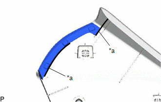
(d) Install the No. 2 rear pillar garnish protector as shown in the illustration. HINT: Install each No. 2 rear pillar garnish protector along the line on the quarter pillar cover sub-assembly. |
|
 Installation
INSTALLATION
CAUTION / NOTICE / HINT
HINT:
Use the same procedure for the RH side and LH side.
The following procedure is for the LH side.
PROCEDURE
1. INSTALL QUARTER PILLAR CO ...
 Radiator Grille
...
Other materials:
Toyota CH-R Service Manual > Pre-collision System: Customize Parameters
CUSTOMIZE PARAMETERS
NOTICE:
When the customer requests a change in a function, first make sure that
the function can be customized.
Make a note of the current settings before customizing.
HINT:
The following PCS functions and the pre-collision system sensitivity setting
...
Toyota CH-R Service Manual > Seat Belt Warning System(w/o Occupant Classification System): Precaution
PRECAUTION
IGNITION SWITCH EXPRESSIONS
HINT:
The type of ignition switch used on this model differs according to the specifications
of the vehicle. The expressions listed in the table below are used in this section.
Expression
Ignition Switch (Position)
Engine ...
Toyota C-HR (AX20) 2023-2026 Owner's Manual
Toyota CH-R Owners Manual
- For safety and security
- Instrument cluster
- Operation of each component
- Driving
- Interior features
- Maintenance and care
- When trouble arises
- Vehicle specifications
- For owners
Toyota CH-R Service Manual
- Introduction
- Maintenance
- Audio / Video
- Cellular Communication
- Navigation / Multi Info Display
- Park Assist / Monitoring
- Brake (front)
- Brake (rear)
- Brake Control / Dynamic Control Systems
- Brake System (other)
- Parking Brake
- Axle And Differential
- Drive Shaft / Propeller Shaft
- K114 Cvt
- 3zr-fae Battery / Charging
- Networking
- Power Distribution
- Power Assist Systems
- Steering Column
- Steering Gear / Linkage
- Alignment / Handling Diagnosis
- Front Suspension
- Rear Suspension
- Tire / Wheel
- Tire Pressure Monitoring
- Door / Hatch
- Exterior Panels / Trim
- Horn
- Lighting (ext)
- Mirror (ext)
- Window / Glass
- Wiper / Washer
- Door Lock
- Heating / Air Conditioning
- Interior Panels / Trim
- Lighting (int)
- Meter / Gauge / Display
- Mirror (int)
- Power Outlets (int)
- Pre-collision
- Seat
- Seat Belt
- Supplemental Restraint Systems
- Theft Deterrent / Keyless Entry

0.0085