Toyota CH-R Service Manual: Removal
REMOVAL
CAUTION / NOTICE / HINT
HINT:
When removing the name plates, heat the vehicle body, back door outside garnish and name plates using a heat light.
Heating Temperature|
Item |
Temperature |
|---|---|
|
Vehicle Body |
40 to 60°C (104 to 140°F) |
|
20 to 30°C (68 to 86°F) |
CAUTION:
- Do not touch the heat light and heated parts, touching the heat light may result in burns.
- Touching heated parts for a long time may result in burns.
.png)
|
*a |
Heated Part |
|
*b |
Heat Light |
NOTICE:
Do not heat the vehicle body, back door outside garnish or name plate excessively.
PROCEDURE
1. REMOVE NO. 2 BACK DOOR NAME PLATE
(a) Apply protective tape around the No. 2 back door name plate as shown in the illustration.
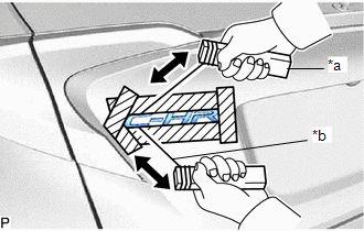
|
*a |
Wooden Block |
|
*b |
Piano Wire |
.png) |
Protective Tape |
(b) Insert a piano wire between the back door outside garnish and No. 2 back door name plate.
(c) Tie objects that can serve as handles (for example, wooden blocks) to both wire ends.
(d) Pull the piano wire and cut the double-sided tape that holds the No. 2 back door name plate to the back door outside garnish to remove the No. 2 back door name plate.
NOTICE:
Be careful not to damage the back door outside garnish.
(e) Remove the protective tape.
2. REMOVE NO. 1 BACK DOOR NAME PLATE
(a) Apply protective tape around the No. 1 back door name plate as shown in the illustration.
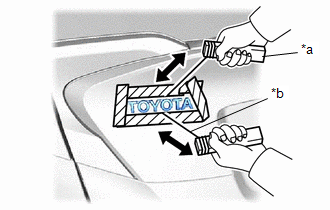
|
*a |
Wooden Block |
|
*b |
Piano Wire |
|
|
Protective Tape |
(b) Insert a piano wire between the back door outside garnish and No. 1 back door name plate.
(c) Tie objects that can serve as handles (for example, wooden blocks) to both wire ends.
(d) Pull the piano wire and cut the double-sided tape that holds the No. 1 back door name plate to the back door outside garnish to remove the No. 1 back door name plate.
NOTICE:
Be careful not to damage the back door outside garnish.
(e) Remove the protective tape.
3. REMOVE NO. 1 BACK DOOR EMBLEM
(a) Apply protective tape around the No. 1 back door emblem as shown in the illustration.
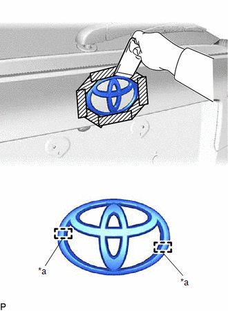
|
*a |
Location Pin |
|
|
Protective Tape |
(b) Using a moulding remover D, separate the double-sided tape and disengage the pins to remove the back door ornament sub-assembly.
NOTICE:
Be careful not to damage the back door outside garnish.
(c) Remove the protective tape.
 Components
COMPONENTS
ILLUSTRATION
*1
NO. 1 BACK DOOR EMBLEM
*2
NO. 1 BACK DOOR NAME PLATE
*3
NO. 2 BACK DOOR NAME PLATE
-
...
 Installation
INSTALLATION
CAUTION / NOTICE / HINT
HINT:
When installing the name plates, heat the back door outside garnish and name
plates using a heat light.
Heating Temperature
Item
...
Other materials:
Toyota CH-R Service Manual > Blind Spot Monitor System: Precaution
PRECAUTION
IGNITION SWITCH EXPRESSIONS
(a) The type of ignition switch used on this model differs depending on the specifications
of the vehicle. The expressions listed in the table below are used in this section.
Expression
Ignition Switch (Position)
Engine Swi ...
Toyota CH-R Service Manual > Rear Wiper Motor: Components
COMPONENTS
ILLUSTRATION
*1
BACK DOOR SIDE GARNISH LH
*2
BACK DOOR SIDE GARNISH RH
*3
BACK DOOR TRIM PANEL ASSEMBLY
*4
BACK DOOR TRIM UPPER PANEL ASSEMBLY
ILLUSTRATION
*1
...
Toyota C-HR (AX20) 2023-2026 Owner's Manual
Toyota CH-R Owners Manual
- For safety and security
- Instrument cluster
- Operation of each component
- Driving
- Interior features
- Maintenance and care
- When trouble arises
- Vehicle specifications
- For owners
Toyota CH-R Service Manual
- Introduction
- Maintenance
- Audio / Video
- Cellular Communication
- Navigation / Multi Info Display
- Park Assist / Monitoring
- Brake (front)
- Brake (rear)
- Brake Control / Dynamic Control Systems
- Brake System (other)
- Parking Brake
- Axle And Differential
- Drive Shaft / Propeller Shaft
- K114 Cvt
- 3zr-fae Battery / Charging
- Networking
- Power Distribution
- Power Assist Systems
- Steering Column
- Steering Gear / Linkage
- Alignment / Handling Diagnosis
- Front Suspension
- Rear Suspension
- Tire / Wheel
- Tire Pressure Monitoring
- Door / Hatch
- Exterior Panels / Trim
- Horn
- Lighting (ext)
- Mirror (ext)
- Window / Glass
- Wiper / Washer
- Door Lock
- Heating / Air Conditioning
- Interior Panels / Trim
- Lighting (int)
- Meter / Gauge / Display
- Mirror (int)
- Power Outlets (int)
- Pre-collision
- Seat
- Seat Belt
- Supplemental Restraint Systems
- Theft Deterrent / Keyless Entry

0.008