Toyota CH-R Service Manual: Disassembly
DISASSEMBLY
PROCEDURE
1. REMOVE RADIATOR GRILLE
Click here
.gif)
2. REMOVE FRONT BUMPER EXTENSION LH
|
(a) Disengage the claws and guide to remove the front bumper extension LH. |
|
3. REMOVE FRONT BUMPER EXTENSION RH
HINT:
Use the same procedure as for the LH side.
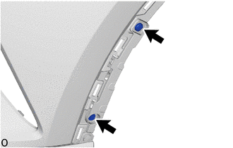
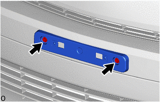
4. REMOVE FOG LIGHT ASSEMBLY LH (w/ Fog Light)
|
(a) Remove the 2 screws. |
|
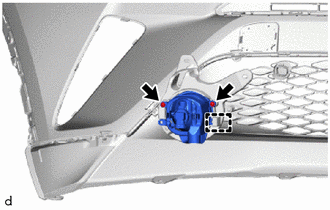
(b) Disengage the guide to remove the fog light assembly LH.
5. REMOVE FOG LIGHT ASSEMBLY RH (w/ Fog Light)
HINT:
Use the same procedure as for the LH side.
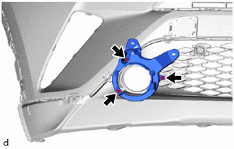
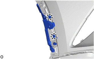
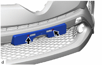
6. REMOVE FOG LIGHT COVER LH
(a) w/ Fog Light:
|
(1) Remove the 3 screws and fog light cover LH. |
|
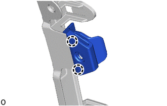
(b) w/o Fog Light:
|
(1) Remove the 3 screws and fog light cover LH. |
|
7. REMOVE FOG LIGHT COVER RH
HINT:
Use the same procedure as for the LH side.
8. REMOVE FRONT BUMPER SIDE MOUNTING BRACKET LH
|
(a) Remove the screw. |
|
(b) Remove the clip.
|
(c) Disengage the claws to remove the front bumper side mounting bracket LH. |
|
9. REMOVE FRONT BUMPER SIDE MOUNTING BRACKET RH
HINT:
Use the same procedure as for the LH side.
10. REMOVE FRONT FENDER LINER RETAINER
|
(a) Disengage the claws to remove the front fender liner retainer. HINT: Use the same procedure for the opposite side. |
|
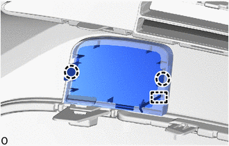
11. REMOVE FRONT BUMPER HOLE COVER
|
(a) Disengage the claws and hook to remove the front bumper hole cover. |
|
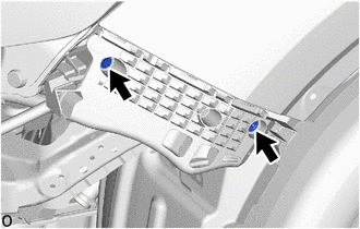
12. REMOVE FRONT BUMPER EXTENSION MOUNTING BRACKET
(a) for USA and Canada:
|
(1) Remove the 2 screws and front bumper extension mounting bracket. |
|
(b) except USA and Canada:
|
(1) Remove the 2 screws. |
|
|
(2) Disengage the claws to remove the front bumper extension mounting bracket. |
|
13. REMOVE INNER RADIATOR GRILLE
|
(a) Disengage the claws to remove the inner radiator grille. |
|
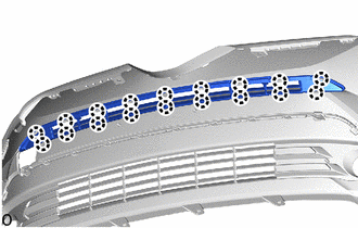
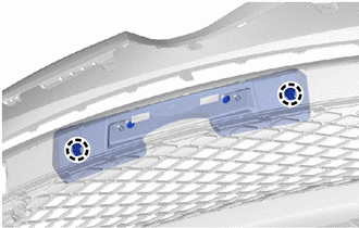
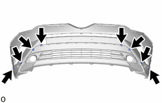
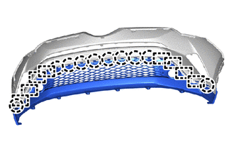
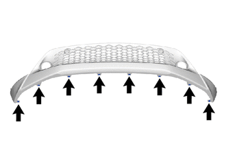
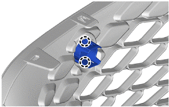
14. REMOVE FRONT BUMPER LOWER COVER
(a) for USA and Canada:
|
(1) Remove the 2 clips and 6 outside moulding retainers. |
|
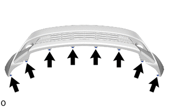
|
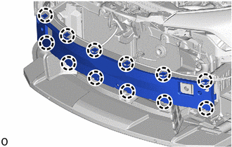
(2) Disengage the claws and guides to remove the front bumper lower cover. |
|
|
(3) Remove the 8 grommets. |
|
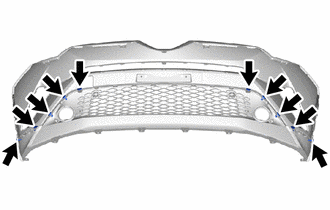
(b) except USA and Canada:
|
(1) Remove the 2 clips and 8 outside moulding retainers. |
|
|
(2) Disengage the claws and guides to remove the front bumper lower cover. |
|
|
(3) Remove the 8 grommets. |
|
15. REMOVE NO. 1 RADIATOR GRILLE MOULDING (except USA and Canada)
|
(a) Disengage the claws to remove the No. 1 radiator grille moulding. HINT: Use the same procedure for the opposite side. |
|
16. REMOVE FRONT BUMPER SIDE RETAINER LH
|
(a) Remove the bolt. |
|
(b) Disengage the claw to remove the front bumper side retainer LH as shown in the illustration.
.png) |
Remove in this Direction |
17. REMOVE FRONT BUMPER SIDE RETAINER RH
HINT:
Use the same procedure as for the LH side.
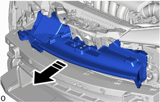
18. REMOVE NO. 1 RADIATOR GRILLE RETAINER
(a) Disengage the claws to remove the No. 1 radiator grille retainer as shown in the illustration.
|
|
Remove in this Direction |
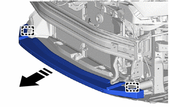
19. REMOVE NO. 1 RADIATOR TO SUPPORT SEAL
|
(a) Disengage the wire harness clamp. |
|
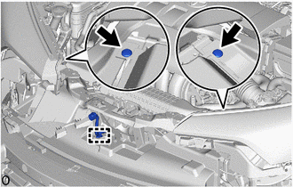
(b) Remove the 2 clips.
(c) Remove the No. 1 radiator to support seal as shown in the illustration.
|
|
Remove in this Direction |
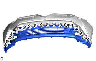
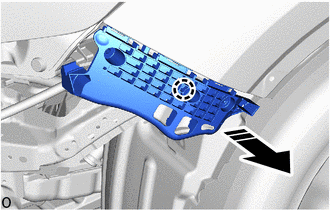
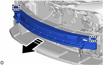
20. REMOVE FRONT BUMPER ENERGY ABSORBER
(a) for USA and Canada:
(1) Disengage the guides to remove the front bumper energy absorber as shown in the illustration.
|
|
Remove in this Direction |
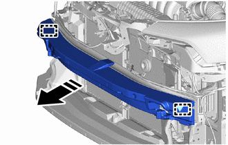
(b) except USA and Canada:
(1) Disengage the guides to remove the front bumper energy absorber as shown in the illustration.
|
|
Remove in this Direction |
21. REMOVE FRONT ENERGY ABSORBER MOUNTING REINFORCEMENT (for USA and Canada)
|
(a) Disengage the claws to remove the front energy absorber mounting reinforcement. |
|
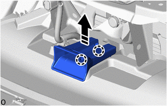
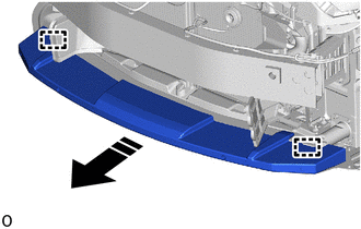
22. REMOVE LOWER FRONT BUMPER ABSORBER
(a) for USA and Canada:
|
|
Remove in this Direction |
(1) Disengage the guides to remove the lower front bumper energy absorber as shown in the illustration.
(b) except USA and Canada:
(1) Disengage the guides to remove the lower front bumper energy absorber as shown in the illustration.
|
|
Remove in this Direction |
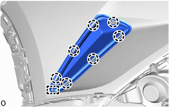
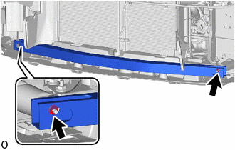
23. REMOVE FRONT BUMPER REINFORCEMENT
(a) for USA and Canada:
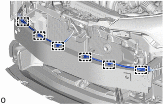
(1) Disengage the wire harness clamps.
|
(2) Remove the 6 bolts. |
|
(3) Disengage the guides to remove the front bumper reinforcement.
(b) except USA and Canada:
|
(1) Disengage the wire harness clamps. |
|
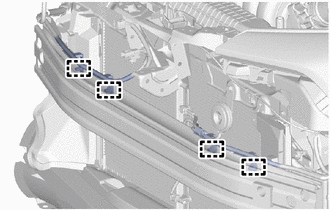
|
(2) Remove the 6 bolts. |
|
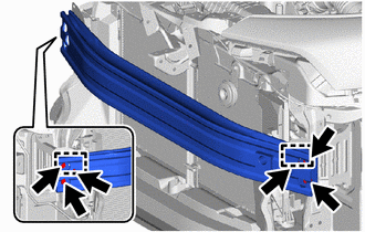
(3) Disengage the guides to remove the front bumper reinforcement.
24. REMOVE FRONT SIDE MEMBER BRACKET SUB-ASSEMBLY LH
(a) for USA and Canada:
|
(1) Remove the 5 bolts. |
|
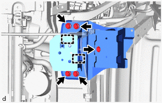
(2) Disengage the guides to remove the front side member bracket sub-assembly LH.
(b) except USA and Canada:
|
(1) Disengage the wire harness clamp. |
|
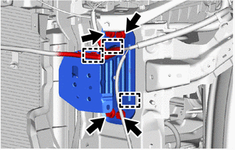
(2) Remove the 4 bolts.
(3) Disengage the guides to remove the front side member bracket sub-assembly LH.
25. REMOVE FRONT SIDE MEMBER BRACKET SUB-ASSEMBLY RH
(a) for USA and Canada:
|
(1) Remove the 4 bolts. |
|
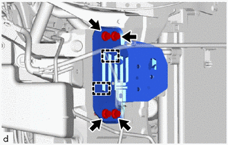
(2) Disengage the guides to remove the front side member bracket sub-assembly RH.
(b) except USA and Canada:
HINT:
Use the same procedure as for the LH side.
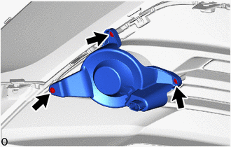
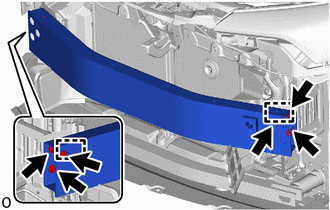
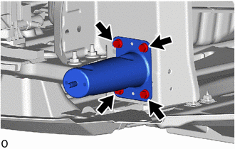
26. REMOVE NO. 2 FRONT BUMPER REINFORCEMENT
|
(a) Remove the 2 nuts and No. 2 front bumper reinforcement. |
|
27. REMOVE FRONT BUMPER BRACKET LH
|
(a) Remove the 4 bolts and front bumper bracket LH. |
|
28. REMOVE FRONT BUMPER BRACKET RH
HINT:
Use the same procedure as for the LH side.
29. REMOVE NO. 1 RADIATOR AIR GUIDE LH
(a) Disengage the claw and guide to remove the No. 1 radiator air guide LH as shown in the illustration.
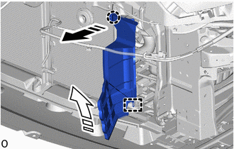
|
|
Remove in this Direction (1) |
.png) |
Remove in this Direction (2) |
30. REMOVE NO. 1 RADIATOR AIR GUIDE RH
(a) Disengage the claw and guide to remove the No. 1 radiator air guide RH as shown in the illustration.
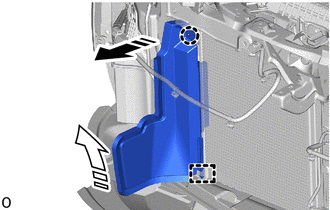
|
|
Remove in this Direction (1) |
|
|
Remove in this Direction (2) |
 Removal
REMOVAL
PROCEDURE
1. REMOVE RADIATOR COVER
(a) Remove the 2 hood bumper cushions.
(b) Remove the 4 clips.
(c) Disengage the guides to re ...
 Installation
INSTALLATION
PROCEDURE
1. INSTALL FRONT BUMPER ASSEMBLY
(a) Move the front bumper assembly into position.
(b) w/ Toyota Safety Sense:
(1) Connect the connector.
(c) Temporarily install the front ...
Other materials:
Toyota CH-R Service Manual > Charging System: How To Proceed With Troubleshooting
CAUTION / NOTICE / HINT
HINT:
*: Use the Techstream.
PROCEDURE
1.
VEHICLE BROUGHT TO WORKSHOP
NEXT
2.
CUSTOMER PROBLEM ANALYSIS
HINT:
In troubleshooting, co ...
Toyota CH-R Service Manual > Occupant Classification Ecu: Installation
INSTALLATION
PROCEDURE
1. INSTALL OCCUPANT DETECTION ECU
(a) Engage the claw to install the occupant detection ECU.
NOTICE:
If the occupant detection ECU has been dropped, or there are any cracks,
dents or other defects in the case or connector, replace the occupant detection ...
Toyota C-HR (AX20) 2023-2026 Owner's Manual
Toyota CH-R Owners Manual
- For safety and security
- Instrument cluster
- Operation of each component
- Driving
- Interior features
- Maintenance and care
- When trouble arises
- Vehicle specifications
- For owners
Toyota CH-R Service Manual
- Introduction
- Maintenance
- Audio / Video
- Cellular Communication
- Navigation / Multi Info Display
- Park Assist / Monitoring
- Brake (front)
- Brake (rear)
- Brake Control / Dynamic Control Systems
- Brake System (other)
- Parking Brake
- Axle And Differential
- Drive Shaft / Propeller Shaft
- K114 Cvt
- 3zr-fae Battery / Charging
- Networking
- Power Distribution
- Power Assist Systems
- Steering Column
- Steering Gear / Linkage
- Alignment / Handling Diagnosis
- Front Suspension
- Rear Suspension
- Tire / Wheel
- Tire Pressure Monitoring
- Door / Hatch
- Exterior Panels / Trim
- Horn
- Lighting (ext)
- Mirror (ext)
- Window / Glass
- Wiper / Washer
- Door Lock
- Heating / Air Conditioning
- Interior Panels / Trim
- Lighting (int)
- Meter / Gauge / Display
- Mirror (int)
- Power Outlets (int)
- Pre-collision
- Seat
- Seat Belt
- Supplemental Restraint Systems
- Theft Deterrent / Keyless Entry

0.0072