Toyota CH-R Service Manual: Removal
REMOVAL
PROCEDURE
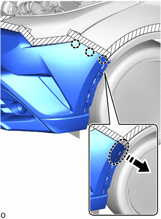
1. REMOVE RADIATOR COVER
|
(a) Remove the 2 hood bumper cushions. |
|
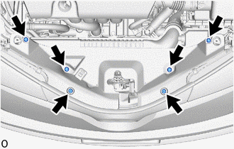
(b) Remove the 4 clips.
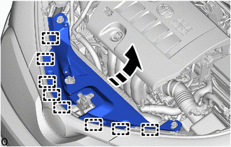
(c) Disengage the guides to remove the radiator cover as shown in the illustration.
.png) |
Remove in this Direction |
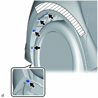
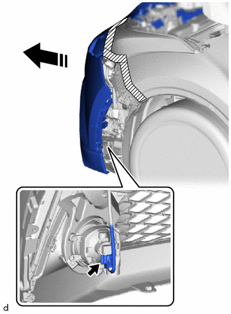
2. SEPARATE FRONT FENDER MOULDING SUB-ASSEMBLY LH
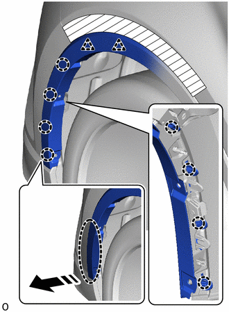
(a) Apply protective tape around the front fender moulding sub-assembly LH.
.png) |
Protective Tape |
(b) Remove the 3 screws.
(c) Remove the 2 clips.
|
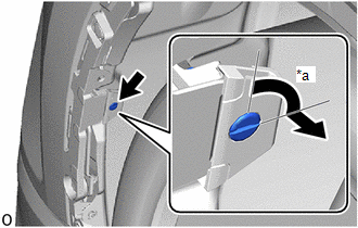
(d) Using a screwdriver, turn the pin 90 degrees and remove the pin hold clip. HINT: Use the same procedure for the RH side and LH side. |
|
(e) Pull back the edge of the front fender liner LH and disengage the claws by pushing the area indicated by the arrow in the illustration with a finger.
.png) |
Place Hand Here |
|
|
Remove in this Direction |
NOTICE:
- Do not apply excessive force when pulling back the front fender liner LH.
- To avoid damaging the claws, do not forcibly pull the front fender moulding sub-assembly LH.
(f) Disengage the clips and separate the front fender moulding sub-assembly LH.
3. SEPARATE FRONT FENDER MOULDING SUB-ASSEMBLY RH
HINT:
Use the same procedure as for the LH side.
4. REMOVE FRONT BUMPER ASSEMBLY
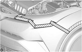
(a) Apply protective tape around the front bumper assembly.
|
|
Protective Tape |
HINT:
Use the same procedure for the RH side and LH side.
|
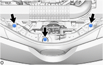
(b) Remove the 3 bolts. |
|
|
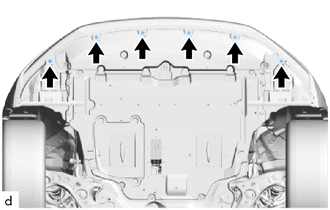
(c) Remove the 6 screws. |
|
(d) Disengage the claws as shown in the illustration.
|
|
Place Hand Here |
|
|
Remove in this Direction |
HINT:
Use the same procedure for the RH side and LH side.
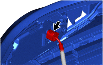
(e) w/ Fog Light:
(1) Pull back the side of the front bumper assembly and disconnect the connector.
NOTICE:
Do not apply excessive force when pulling back the front bumper assembly.
HINT:
Use the same procedure for the RH side and LH side.
|
|
Remove in this Direction |
|
(f) w/ Toyota Safety Sense: (1) Disconnect the connector. |
|
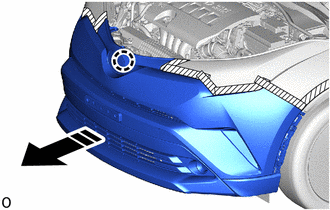
(g) Disengage the claw to remove front bumper assembly as shown in the illustration.
|
|
Remove in this Direction |
 Components
COMPONENTS
ILLUSTRATION
*1
FRONT BUMPER ASSEMBLY
*2
FRONT FENDER MOULDING SUB-ASSEMBLY LH
*3
FRONT FENDER MOULDING SUB-ASSEM ...
 Disassembly
DISASSEMBLY
PROCEDURE
1. REMOVE RADIATOR GRILLE
Click here
2. REMOVE FRONT BUMPER EXTENSION LH
(a) Disengage the claws and guide to remove the front bumper extension
LH.
...
Other materials:
Toyota CH-R Service Manual > Rear Airbag Sensor: Removal
REMOVAL
CAUTION / NOTICE / HINT
The necessary procedures (adjustment, calibration, initialization, or registration)
that must be performed after parts are removed, installed, or replaced during the
No. 2 side airbag sensor removal/installation are shown below.
Necessary Procedure After Parts ...
Toyota CH-R Service Manual > Fog Light Assembly: Adjustment
ADJUSTMENT
PROCEDURE
1. PREPARE VEHICLE FOR FOG LIGHT AIM ADJUSTMENT
(a) Prepare the vehicle:
Ensure that there is no damage or deformation to the vehicle body around
the fog lights.
Fill the fuel tank.
Make sure that the oil is filled to the specified level.
Make sure tha ...
Toyota C-HR (AX20) 2023-2026 Owner's Manual
Toyota CH-R Owners Manual
- For safety and security
- Instrument cluster
- Operation of each component
- Driving
- Interior features
- Maintenance and care
- When trouble arises
- Vehicle specifications
- For owners
Toyota CH-R Service Manual
- Introduction
- Maintenance
- Audio / Video
- Cellular Communication
- Navigation / Multi Info Display
- Park Assist / Monitoring
- Brake (front)
- Brake (rear)
- Brake Control / Dynamic Control Systems
- Brake System (other)
- Parking Brake
- Axle And Differential
- Drive Shaft / Propeller Shaft
- K114 Cvt
- 3zr-fae Battery / Charging
- Networking
- Power Distribution
- Power Assist Systems
- Steering Column
- Steering Gear / Linkage
- Alignment / Handling Diagnosis
- Front Suspension
- Rear Suspension
- Tire / Wheel
- Tire Pressure Monitoring
- Door / Hatch
- Exterior Panels / Trim
- Horn
- Lighting (ext)
- Mirror (ext)
- Window / Glass
- Wiper / Washer
- Door Lock
- Heating / Air Conditioning
- Interior Panels / Trim
- Lighting (int)
- Meter / Gauge / Display
- Mirror (int)
- Power Outlets (int)
- Pre-collision
- Seat
- Seat Belt
- Supplemental Restraint Systems
- Theft Deterrent / Keyless Entry

0.0072