Toyota CH-R Service Manual: On-vehicle Inspection
ON-VEHICLE INSPECTION
PROCEDURE
1. INSPECT HOOD SUB-ASSEMBLY
(a) Check that the clearance measurements of areas "A" to "H" are within the standard ranges.
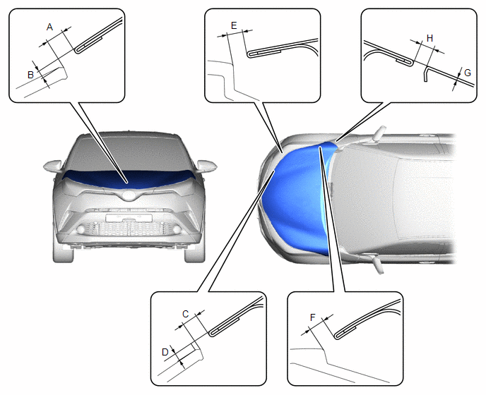 Standard Clearance
|
Area |
Measurement |
Area |
Measurement |
|---|---|---|---|
|
A |
2.8 to 5.8 mm (0.110 to 0.228 in.) |
B |
0.5 to 3.5 mm (0.020 to 0.138 in.) |
|
C |
2.8 to 5.8 mm (0.110 to 0.228 in.) |
D |
0.5 to 3.5 mm (0.020 to 0.138 in.) |
|
E |
1.8 to 5.8 mm (0.071 to 0.228 in.) |
F |
1.8 to 5.8 mm (0.071 to 0.228 in.) |
|
G |
-1.5 to 1.5 mm (-0.059 to 0.059 in.) |
H |
3.4 to 6.4 mm (0.134 to 0.252 in.) |
 Components
COMPONENTS
ILLUSTRATION
*1
HOLE PLUG
*2
HOOD INSULATOR
*3
HOOD SIDE PANEL LH
*4
HOOD SIDE PANEL RH
...
 Disassembly
DISASSEMBLY
PROCEDURE
1. REMOVE HOOD SIDE PANEL LH
(a) Using a clip remover, disengage the clips to remove the hood side
panel LH.
2. ...
Other materials:
Toyota CH-R Service Manual > Windshield Deicer System: Precaution
PRECAUTION
IGNITION SWITCH EXPRESSIONS
(a) The type of ignition switch used on this model differs according to the specifications
of the vehicle. The expressions listed in the table below are used in this section.
Expression
Ignition Switch (Position)
Engine Swi ...
Toyota CH-R Service Manual > Front Disc Brake Pad: Removal
REMOVAL
CAUTION / NOTICE / HINT
NOTICE:
Immediately after installing the brake pads, the braking performance
may be reduced. Always perform a road test in a safe place while paying
attention to the surroundings.
Immediately after installing the front disc brake pads, the brake ...
Toyota C-HR (AX20) 2023-2026 Owner's Manual
Toyota CH-R Owners Manual
- For safety and security
- Instrument cluster
- Operation of each component
- Driving
- Interior features
- Maintenance and care
- When trouble arises
- Vehicle specifications
- For owners
Toyota CH-R Service Manual
- Introduction
- Maintenance
- Audio / Video
- Cellular Communication
- Navigation / Multi Info Display
- Park Assist / Monitoring
- Brake (front)
- Brake (rear)
- Brake Control / Dynamic Control Systems
- Brake System (other)
- Parking Brake
- Axle And Differential
- Drive Shaft / Propeller Shaft
- K114 Cvt
- 3zr-fae Battery / Charging
- Networking
- Power Distribution
- Power Assist Systems
- Steering Column
- Steering Gear / Linkage
- Alignment / Handling Diagnosis
- Front Suspension
- Rear Suspension
- Tire / Wheel
- Tire Pressure Monitoring
- Door / Hatch
- Exterior Panels / Trim
- Horn
- Lighting (ext)
- Mirror (ext)
- Window / Glass
- Wiper / Washer
- Door Lock
- Heating / Air Conditioning
- Interior Panels / Trim
- Lighting (int)
- Meter / Gauge / Display
- Mirror (int)
- Power Outlets (int)
- Pre-collision
- Seat
- Seat Belt
- Supplemental Restraint Systems
- Theft Deterrent / Keyless Entry

0.0077