Toyota CH-R Service Manual: Parts Location
PARTS LOCATION
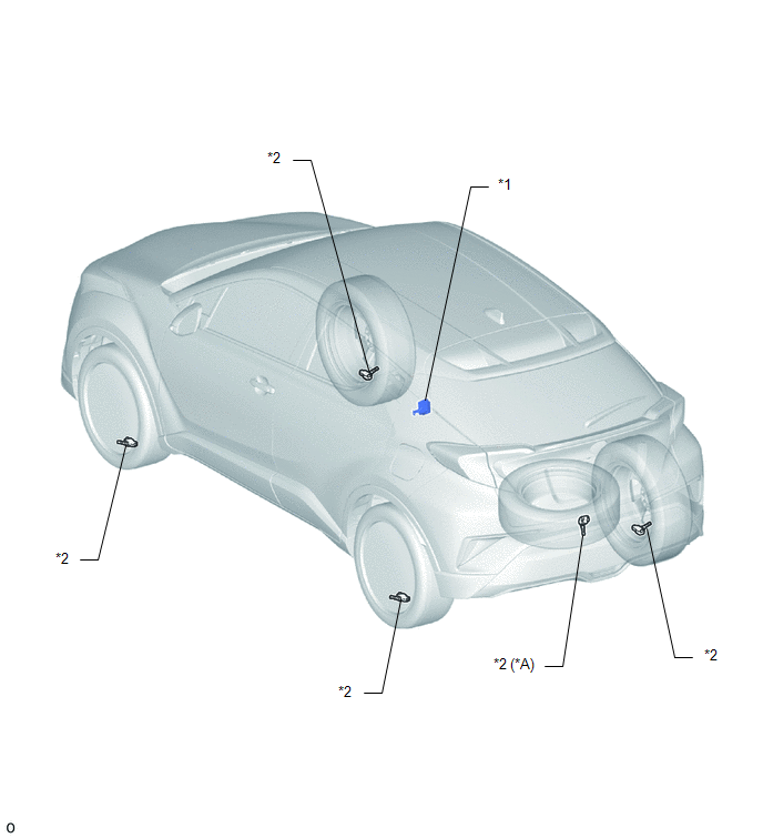
ILLUSTRATION
|
*A |
w/ Full Size Spare Tire |
- |
- |
|
*1 |
TIRE PRESSURE WARNING ECU AND RECEIVER |
*2 |
TIRE PRESSURE WARNING VALVE AND TRANSMITTER |
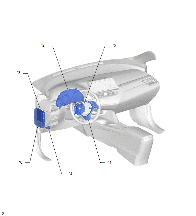
ILLUSTRATION
|
*1 |
STEERING PAD SWITCH ASSEMBLY |
*2 |
COMBINATION METER ASSEMBLY |
|
*3 |
MAIN BODY ECU (MULTIPLEX NETWORK BODY ECU) |
*4 |
DLC3 |
|
*5 |
SPIRAL CABLE SUB-ASSEMBLY |
*6 |
INSTRUMENT PANEL JUNCTION BLOCK ASSEMBLY - ECU-IG1 NO. 4 FUSE - ECU-B NO. 2 FUSE |
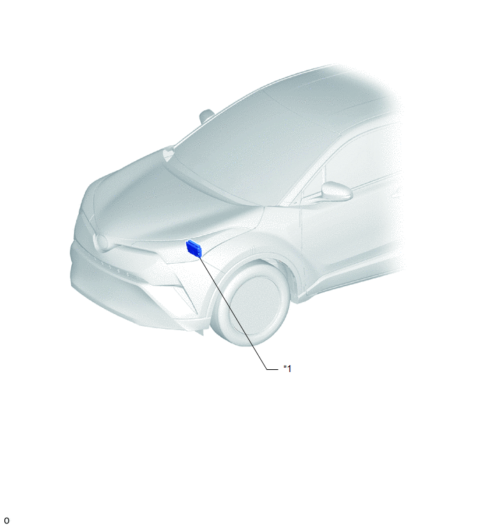
ILLUSTRATION
|
*1 |
ECM |
- |
- |
 Precaution
PRECAUTION
IGNITION SWITCH EXPRESSIONS
(a) The type of ignition switch used on this model differs according to the specifications
of the vehicle. The expressions listed in the table below are used ...
 System Diagram
SYSTEM DIAGRAM
HINT:
Each tire pressure warning valve and transmitter sends its transmitter ID, temperature
and tire pressure information to the tire pressure warning ECU and receiver.
...
Other materials:
Toyota CH-R Service Manual > Back Door Glass: Installation
INSTALLATION
PROCEDURE
1. CLEAN BACK DOOR GLASS
(a) When reusing the back door glass:
(1) Using a scraper, remove any remaining adhesive residue from the back
window glass.
NOTICE:
Be careful not to damage the back window glass.
(2) Clean the outer circumference of the ...
Toyota CH-R Service Manual > Front Seat Inner Belt Assembly: Removal
REMOVAL
CAUTION / NOTICE / HINT
The necessary procedures (adjustment, calibration, initialization, or registration)
that must be performed after parts are removed and installed, or replaced during
the front seat inner belt assembly removal/installation are shown below.
Necessary Procedure Aft ...
Toyota C-HR (AX20) 2023-2026 Owner's Manual
Toyota CH-R Owners Manual
- For safety and security
- Instrument cluster
- Operation of each component
- Driving
- Interior features
- Maintenance and care
- When trouble arises
- Vehicle specifications
- For owners
Toyota CH-R Service Manual
- Introduction
- Maintenance
- Audio / Video
- Cellular Communication
- Navigation / Multi Info Display
- Park Assist / Monitoring
- Brake (front)
- Brake (rear)
- Brake Control / Dynamic Control Systems
- Brake System (other)
- Parking Brake
- Axle And Differential
- Drive Shaft / Propeller Shaft
- K114 Cvt
- 3zr-fae Battery / Charging
- Networking
- Power Distribution
- Power Assist Systems
- Steering Column
- Steering Gear / Linkage
- Alignment / Handling Diagnosis
- Front Suspension
- Rear Suspension
- Tire / Wheel
- Tire Pressure Monitoring
- Door / Hatch
- Exterior Panels / Trim
- Horn
- Lighting (ext)
- Mirror (ext)
- Window / Glass
- Wiper / Washer
- Door Lock
- Heating / Air Conditioning
- Interior Panels / Trim
- Lighting (int)
- Meter / Gauge / Display
- Mirror (int)
- Power Outlets (int)
- Pre-collision
- Seat
- Seat Belt
- Supplemental Restraint Systems
- Theft Deterrent / Keyless Entry

0.0129